
Accesorios de Electrofusión HDPE: Cómo Seleccionar el Adecuado
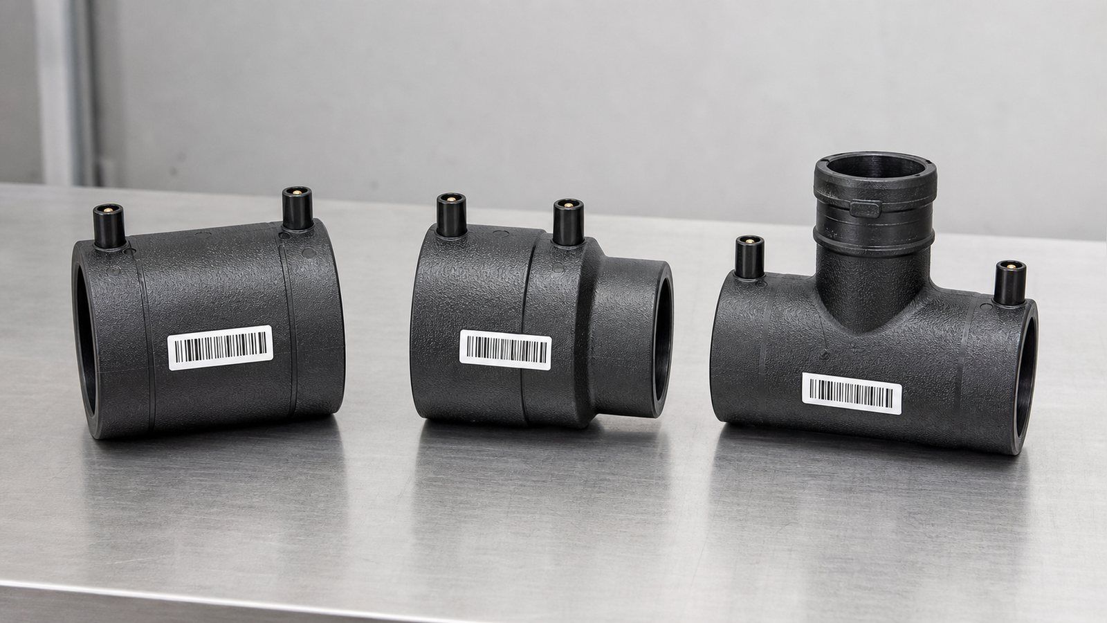
Cómo elegir accesorios de electrofusión HDPE: coincidencia de SDR y clase de presión, acoplador vs. derivación con te, códigos de barras ISO 13950 y límites de ovalidad.
Elegir accesorios de electrofusión de HDPE parece un ejercicio de catálogo hasta que la primera unión falla en una prueba de presión. Busque el término y aterrizará casi por completo en cuadrículas de productos: acopladores a 230 psi, reductores por pulgada, tees de derivación por tamaño de salida, con casi nada que le indique cuál de esas piezas corresponde a su tubería, o qué debe ser cierto sobre la tubería antes de que cualquiera de ellas pueda fusionarse. El número de pieza es la mitad fácil de la decisión. La mitad que decide si la unión se mantiene es la coincidencia entre el accesorio, la tubería que realmente tiene en el sitio y las tolerancias que el accesorio asume silenciosamente.

Conclusiones clave
- Los accesorios de electrofusión pueden unir diferentes grados de PE y diferentes SDR, pero el sistema terminado se clasifica según el componente de menor clasificación en la unión: verifique el PN de cada pieza, no solo el de la tubería.
- Una tee de derivación y una silla de derivación no son sinónimos: ISO 4427-3 define la tee de derivación como aquella que lleva un cortador integral que permanece en el accesorio, mientras que una silla de derivación necesita una herramienta de corte separada.
- ISO 13950 permite dos formatos de código de barras: de 24 dígitos y de 32 dígitos, y solo la versión de 32 dígitos lleva codificación de trazabilidad. Si necesita trazabilidad por unión, debe especificarla.
- El raspado tiene un máximo además de un mínimo: deben retirarse 0.007 pulgadas, pero la profundidad total de pelado se limita a 0.014 pulgadas en tubería de 3/4 pulgada y a 0.027 pulgadas en tubería de 6 a 12 pulgadas.
- Las abrazaderas de re-redondeo se convierten en un requisito real desde 3 pulgadas IPS/DIPS hacia arriba; por debajo de 2 pulgadas, el acoplador y las abrazaderas de alineación generalmente redondean la tubería por sí solos.
- Una ventana de instalación calificada típica es de 14°F a 113°F (aproximadamente -10°C a 45°C), y la tubería negra bajo el sol directo puede alcanzar 70°C, muy por fuera de ese rango.
- Los indicadores de fusión elevados confirman que se desarrolló la presión de fusión. Explícitamente no son confirmación de una soldadura exitosa.
Cuándo la electrofusión justifica su sobrecosto
Un accesorio de electrofusión cuesta varias veces más que un acoplador de compresión del mismo diámetro, y necesita una caja de control, un generador, una herramienta de pelado y abrazaderas antes de que pueda hacer nada. Esa diferencia de precio es lo primero que nota un comprador y lo último que explica un catálogo. La respuesta honesta es que la electrofusión no es un método de unión de uso general que se elige por defecto; es el método que se elige cuando las alternativas están bloqueadas por algo físico.
La condición que bloquea suele ser el espacio. La fusión a tope necesita suficiente longitud libre en ambos lados de la unión para introducir una máquina, sujetar los dos extremos del tubo y mantenerlos alineados mientras se enfrían. En una zanja congestionada, contra una tubería existente, en una reparación donde no se puede mover ninguno de los extremos, o en una conexión de derivación donde no hay ningún extremo de tubería, esa holgura no existe.
Un acoplador de electrofusión trabaja completamente desde el exterior del tubo y solo necesita espacio suficiente para deslizarse sobre los extremos, por lo que domina en reparaciones, empalmes y conexiones de servicio. La contrapartida es que la electrofusión traslada toda la carga de calidad a la preparación de la superficie, mientras que la fusión a tope la traslada a la configuración de la máquina.
La segunda razón se discute mucho menos y le importa más a la adquisición que a los instaladores. La electrofusión tolera una discrepancia que la fusión a tope no tolera. La fusión a tope requiere que los dos extremos del tubo tengan el mismo diámetro exterior y el mismo espesor de pared, por lo que unir un tubo PE80 SDR11 con un tubo PE100 SDR17 de extremo a extremo no es una operación normal. Los accesorios de electrofusión trabajan solo en la superficie exterior, por lo que, como dice la guía de electrofusión de la Plastics Industry Pipe Association, la soldadura "se puede utilizar para unir tubos fabricados con diferentes grados de material PE (es decir, PE80 y PE100) y diferentes Relaciones de Dimensiones Estándar (SDR)".
En una red que se ha ampliado por fases durante quince años con lo que había disponible en cada momento, esa flexibilidad no es un lujo: es la única forma práctica de conectar el trabajo antiguo con el nuevo.
Esa flexibilidad viene con una regla adjunta, y es la regla en la que se basa toda esta guía. Se cubre en la siguiente sección, y equivocarse es cómo un comprador termina con una unión técnicamente sólida en un sistema que ya no soporta la presión para la que fue diseñado.
SDR, grado y clase de presión: la regla de compatibilidad que lo gobierna todo
Los accesorios de electrofusión se dimensionan según el diámetro exterior, y la tubería de PE de un diámetro nominal determinado tiene el mismo diámetro exterior en cada SDR; el espesor de pared cambia hacia adentro. Por eso un solo número de pieza de acoplador puede servir para un rango de SDR, y por qué "¿este accesorio encajará en mi tubería?" tiene una respuesta más simple de lo que la mayoría de los compradores esperan: si el diámetro exterior coincide y el rango de SDR indicado del accesorio incluye el suyo, encaja.
Si funciona o no es otra cuestión. PIPA establece la regla general con claridad: "Cuando se utilizan diferentes materiales o SDR, la clasificación PN del sistema de tuberías es equivalente a la del componente de tubería o accesorio con la clasificación más baja".
Un accesorio PN16 en tubería PN10 le da un sistema PN10. Un accesorio PN10 en tubería PN16 también le da un sistema PN10, y ese segundo caso es el costoso, porque el comprador pagó por tubería PN16 y silenciosamente redujo la clasificación de la red en cada unión. Cuando usted está cotizando accesorios contra una lista de materiales, la clase de presión del accesorio no es un detalle de especificación que se pueda reducir para obtener margen. Es el techo de todo lo que toca.
El modo de falla subyacente es un problema de nomenclatura. El SDR es una relación geométrica (diámetro exterior dividido por espesor de pared) y no es una clasificación de presión por sí sola, porque la misma relación en un compuesto más débil produce una clase más baja.
La propia página de especificaciones de HDPE de IFAN establece la correspondencia y luego señala la trampa directamente: en PE100, "SDR11 da PN16, SDR17 da PN10, SDR21 da PN8 y SDR26 da PN6.3", mientras que "SDR11 en PE80 es PN12.5, no PN16", lo que IFAN describe como "el error de especificación más común que vemos en las consultas entrantes". Un comprador que pide "accesorios SDR11" creyendo que ha pedido PN16 no ha especificado nada sobre la presión hasta que se nombre el grado junto con él.
| SDR | Clase de presión en PE100 | Qué significa cuando se mezclan |
|---|---|---|
| SDR11 | PN16 (PE80: PN12.5) | Clase más alta aquí; cualquier accesorio de menor clasificación en la unión establece la clase del sistema en su lugar |
| SDR17 | PN10 | Elección común para tuberías de distribución; verifique que el accesorio no sea el eslabón débil |
| SDR21 | PN8 | Pared más delgada; confirme que el rango de SDR del accesorio llegue hasta aquí |
| SDR26 | PN6.3 | La pared delgada se rigidiza menos; la ovalidad y el re-redondeo importan más aquí |
Dos consecuencias prácticas se derivan de esto. Primero, ponga el grado de PE, el SDR y el PN en cada línea de la orden de compra, por separado para tubería y accesorios: "DN110 PE100 SDR17 PN10" no deja nada a la interpretación, y "DN110 SDR17" deja el grado abierto.
Segundo, cuando un accesorio se cotiza con un rango de SDR en lugar de un solo SDR, pregunte contra qué extremo de ese rango se establece la clase de presión. La instrucción de PIPA al respecto es "siempre verifique el código de barras o el empaque del accesorio y consulte al fabricante si no está seguro", lo cual es una forma educada de decir que el rango impreso en un catálogo web no es una especificación sobre la que deba construir una red. La misma disciplina se aplica al resto de la gama de productos HDPE y PE: el grado y la clase pertenecen a la documentación, no a una suposición.
Acoplamiento, reductor, toma en carga o derivación de silla: elija según la función de la unión
La mayoría de los catálogos los presentan uno al lado del otro como si la elección fuera solo de forma. No lo es. La norma ISO 4427-3:2019 divide los accesorios de electrofusión en dos familias estructuralmente diferentes, y esta división determina el equipo que necesita, el tiempo de enfriamiento que debe programar y si puede trabajar en una tubería en servicio o no.
Accesorios de enchufe: acoplamientos y reductores
La norma ISO 4427-3 define un accesorio de electrofusión de enchufe como aquel que "contiene uno o más elementos calefactores integrales capaces de transformar energía eléctrica en calor para realizar una unión por fusión con un extremo de espiga o tubería". En términos simples, la tubería se inserta dentro del accesorio. Los acoplamientos rectos unen dos tuberías del mismo diámetro; los reductores unen dos diámetros diferentes en una sola pieza.
Un reductor es la opción correcta cuando el cambio de diámetro y la unión ocurren en el mismo lugar. Cuando no es así, un acoplamiento recto más un tramo de tubería reducido suele ser más económico y siempre más fácil de conseguir, porque los reductores son la pieza que más probablemente falte en el estante del distribuidor en la combinación de tamaños que necesita.
Accesorios de silla: tomas en carga y derivaciones de silla
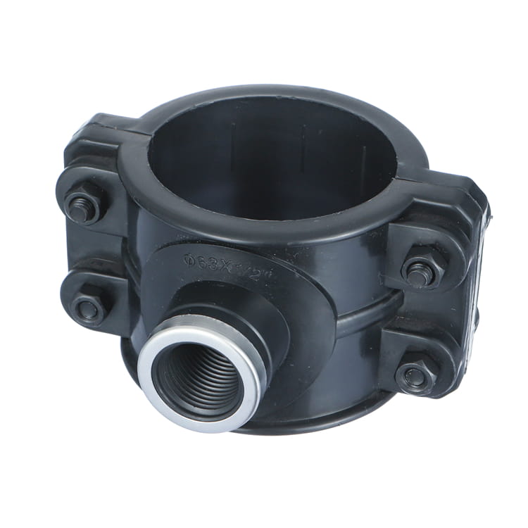
Los accesorios de silla se fusionan en el exterior de la tubería en lugar de alrededor de su extremo, lo que permite derivar de una tubería principal sin cortarla. Aquí, la norma ISO 4427-3 hace una distinción que la mayoría de las páginas de producto difuminan, y tiene consecuencias directas en el costo. Una toma en carga es una silla "que contiene un cortador integral utilizado para cortar la pared de la tubería principal, que permanece en el cuerpo de la toma en carga después de la instalación". Una derivación de silla es una silla "que requiere una herramienta de corte auxiliar para perforar el agujero en la tubería principal adyacente".
Lea esa diferencia como una instrucción de compra. La toma en carga lleva su cortador consigo, por lo que cada unidad es autónoma y el agujero se realiza después de que la fusión se haya enfriado, lo que hace posible la toma en carga bajo presión en una tubería en servicio. La derivación de silla es más barata por unidad porque el cortador no está incluido, pero debe poseer la herramienta de perforación y la tubería principal debe despresurizarse y perforarse como una operación separada. Comprar derivaciones de silla para ahorrar costo unitario, en un proyecto donde la tubería principal no puede sacarse de servicio, es un error de especificación que se manifiesta en obra, no en la etapa de cotización.
Hay una segunda división dentro de la familia de sillas que determina el equipo. PIPA describe las sillas de abrazadera inferior como accesorios que "envuelven completamente la tubería, con una abrazadera integral" y señala que "a menudo se usan con sillas de toma en carga en vivo", mientras que las sillas de carga superior necesitan "una herramienta de montaje específica del fabricante para posicionar y sujetar de manera segura el accesorio durante la soldadura", y esa herramienta "se retira de la unión preparada después de cada proceso de soldadura y enfriamiento".
La frase a tener en cuenta es específica del fabricante. Si compra sillas de montar superiores de dos marcas en un mismo proyecto, necesitará dos juegos de herramientas de montaje, y un equipo que tome la herramienta equivocada perderá la unión. Estandarizar la marca de la silla de montar en todo el proyecto vale más que la diferencia de precio unitario entre marcas.
| Accesorio | Elíjalo cuando | Tenga cuidado con |
|---|---|---|
| Acoplamiento recto | Reparaciones, empalmes, zanjas congestionadas, mismo diámetro en ambos lados | Requiere que ambos extremos de la tubería estén lo suficientemente libres para deslizar el acoplamiento |
| Acoplamiento reductor | El cambio de diámetro y la unión ocurren en el mismo punto | Largos plazos de entrega en pares de tamaños poco comunes; confirme la disponibilidad antes de diseñar en torno a ello |
| Tee de derivación (tapping tee) | Derivar de una tubería principal que no puede cerrarse; el cortador debe ser integral | Mayor costo unitario; el cortador permanece en el accesorio permanentemente |
| Silla de montar para derivación | Derivaciones planificadas en una tubería principal que se puede despresurizar | Debe poseer la herramienta de corte separada; no es para derivación en vivo |
Rango de diámetros: dónde se ubica realmente su tamaño
En las conversaciones sobre electrofusión se citan dos rangos de diámetros diferentes y no son intercambiables. Uno es el rango de tubería de PE que un proveedor puede producir. El otro es el rango en el que los accesorios de electrofusión se almacenan comúnmente y en el que los procedimientos de instalación publicados realmente se aplican. Los compradores se ven atrapados cuando leen el primer número y planifican según el segundo.
En el lado de la tubería, la especificación HDPE publicada por IFAN da un rango de diámetro exterior de "DN20 – DN1600 (PE100)", suministrado como "bobinas hasta DN90; barras rectas de 6 m y 12 m". Ese límite de bobina DN90 vale la pena tenerlo en cuenta, porque predice un problema en lugar de describir un producto. La tubería en bobina lleva curvatura residual y llega ovalada, que es la razón más común por la que una unión por electrofusión necesita abrazaderas de recalibrado y trabajo de alineación. Todo lo que esté en DN90 o por debajo probablemente llegue a la obra en bobina; todo lo que esté por encima llega recto. Si su lista de materiales se encuentra principalmente por debajo de DN90, presupueste el trabajo de geometría descrito más adelante en esta guía.
En el lado del procedimiento, los límites de alcance importan más que los rangos de marketing. El procedimiento de la Junta Asesora Municipal del Plastics Pipe Institute — el documento al que la mayoría de las empresas de servicios públicos de América del Norte remiten a sus cuadrillas — está titulado para "Unión en Campo de Tubería de Polietileno (PE) de 12 Pulgadas y Menores", y sus tablas de tiempo de enfriamiento y ovalidad se detienen en 12 pulgadas. Por encima de ese tamaño, se encuentra fuera del procedimiento genérico y dentro de las instrucciones específicas del fabricante, que es exactamente donde un comprador debe dejar de asumir y comenzar a preguntar al proveedor por el procedimiento escrito que cubre el diámetro en el plano.
La conclusión práctica para dimensionar una compra es que el diámetro cambia las preguntas que debe hacer, no solo el número de pieza que pide. Los diámetros pequeños provocan ovalidad inducida por la bobina. Los diámetros grandes lo llevan más allá del procedimiento genérico, añaden herramientas de recalibrado y alargan los tiempos de enfriamiento hasta una hora por unión. Ninguno de los dos es motivo para evitar la electrofusión; ambos son motivos para valorar la mano de obra y las herramientas con honestidad, en lugar de asumir que un accesorio es un accesorio.
El código de barras es un control de calidad, no una conveniencia
Cada accesorio de electrofusión lleva una etiqueta con un código de barras, y la mayoría de los compradores lo tratan como una característica de conveniencia que evita que el operador tenga que escribir. Es considerablemente más que eso, y el estándar detrás de él es uno que un comprador puede nombrar en una especificación.
ISO 13950:2007 es el estándar que lo rige. Su alcance cubre "las características de los sistemas de reconocimiento automático (reconocimiento numérico mediante códigos de barras o tarjetas magnéticas, reconocimiento electromecánico mediante conectores de resistencia implantada y sistemas de autorregulación) que permiten que el suministro de energía se entregue automáticamente a los accesorios de electrofusión termoplásticos utilizados en la unión de tuberías." Reemplazó el informe técnico anterior ISO/TR 13950:1997, por lo que un proveedor que cite el documento de 1997 está citando algo que fue reemplazado hace casi dos décadas.
Dos parámetros físicos de ese estándar merecen ser citados de vuelta a un proveedor, porque se pueden verificar en una etiqueta impresa en lugar de confiar en ellos. Ambos formatos permitidos son códigos intercalados "2 de 5" con una relación de ancho de barra gruesa a delgada especificada de 2,5 — una tolerancia de impresión, y una etiqueta mal reproducida que no la cumpla es una etiqueta que un escáner puede rechazar en una zanja húmeda. Y el código lleva una suma de verificación interna, por lo que un dígito mal tecleado falla en lugar de cargar silenciosamente el tiempo de fusión incorrecto en la caja.
El detalle que pertenece a su orden de compra es el formato. ISO 13950 permite exactamente dos, y no son equivalentes. El estándar especifica "el tipo intercalado '2 de 5' de 24 dígitos" y "el tipo intercalado '2 de 5' de 32 dígitos, incluida la codificación de trazabilidad" — en ambos casos con una relación de ancho de barra gruesa a delgada de 2,5, y con una longitud total donde "uno de estos dígitos está compuesto por un carácter de control (suma de verificación)."
Solo el formato de 32 dígitos lleva codificación de trazabilidad. Si su proyecto, su cliente de servicios públicos o su propio sistema de calidad requieren trazabilidad por unión hasta un lote específico de accesorios, un código de barras de 24 dígitos no lo proporcionará, y ninguna cantidad de pedirle al instalador que escriba las cosas lo añadirá retroactivamente. Esa es una pregunta que debe resolverse con el proveedor antes del pedido, no un descubrimiento que hacer durante la puesta en marcha.
Lo que hace el código de barras en el momento de la fusión es el argumento más fuerte para insistir en él.La guía del usuario de electrofusión de PPIdescribe la caja de control que realiza "comprobaciones básicas antes de comenzar la fusión para verificar que la bobina del accesorio tiene continuidad, que la resistencia de la bobina coincide con la información del código de barras y que el voltaje suministrado es suficiente", y durante el ciclo detecta "ciertos errores de ensamblaje o de accesorio, como bobinas de calentamiento en cortocircuito o extremos de tubería insertados a poca profundidad".
Una verificación cruzada de resistencia contra el código de barras escaneado detecta un accesorio falsificado o mal etiquetado antes de que cualquier energía llegue a la unión. La entrada manual del tiempo de fusión y del voltaje omite esa comparación por completo: la caja hace lo que se le indica. PIPA añade que "las máquinas de soldadura con lectura de código de barras ajustan automáticamente las condiciones de temperatura ambiente variables", algo que la entrada manual también pierde.
Esa corrección de temperatura merece la pena cuantificarla, porque es la comprobación que más a menudo se pierde cuando el personal introduce los parámetros a mano. La ventana de instalación cualificada va aproximadamente de -10°C a 45°C, y un accesorio fusionado a 5°C necesita una entrada de energía materialmente diferente del mismo accesorio fusionado a 40°C.
Un código de barras escaneado aplica esa corrección automáticamente; un tiempo de soldadura introducido a mano aplica el número que el operario leyó en la etiqueta, a la temperatura que tenga la zanja en ese momento. En un acoplador DN315 con un tiempo de enfriamiento de 60 minutos, el coste de hacerlo mal no es una unión: es una hora de tiempo de cuadrilla por cada re-soldadura, y hasta 24 horas antes de que el conjunto baje de 45°C si la unión tiene que re-fusionarse.
Dos detalles de apoyo merecen la pena conocerse. El valor de 24 dígitos también está "impreso en la etiqueta, ya sea directamente encima o debajo del código de barras", por lo que un código de barras dañado o ilegible no deja la unión en tierra: el operario puede teclear los dígitos y la suma de verificación sigue detectando un error tipográfico. Y la máquina en sí tiene una norma: PIPA especifica que las máquinas de soldadura "fabricadas de acuerdo con ISO 12176-2" que "funcionan con accesorios marcados con código de barras según ISO 13950", con un dispositivo de seguridad que "debe actuar en menos de 0,5 segundos". Esos dos números de norma, ISO 13950 para el accesorio e ISO 12176-2 para la máquina, son el par que hay que incluir en un pliego de condiciones.
Falta de redondez, zonas planas y convergencia: el control geométrico
Un accesorio de electrofusión funciona fundiendo ambas superficies y dejando que la expansión del polietileno fundido cierre el hueco anular entre la tubería y el casquillo. Ese mecanismo tiene un límite. Si el hueco es demasiado ancho antes de empezar, la expansión del fundido no puede cerrarlo, y MAB-1 es explícito sobre la consecuencia: cuando la tubería está ovalada y no se corrige, "la cantidad de hueco entre la tubería y el accesorio puede ser demasiado grande para que la expansión del fundido lo cierre". El accesorio seguirá ejecutando su ciclo. Los pasadores seguirán subiendo. La unión quedará hueca en algunos puntos.
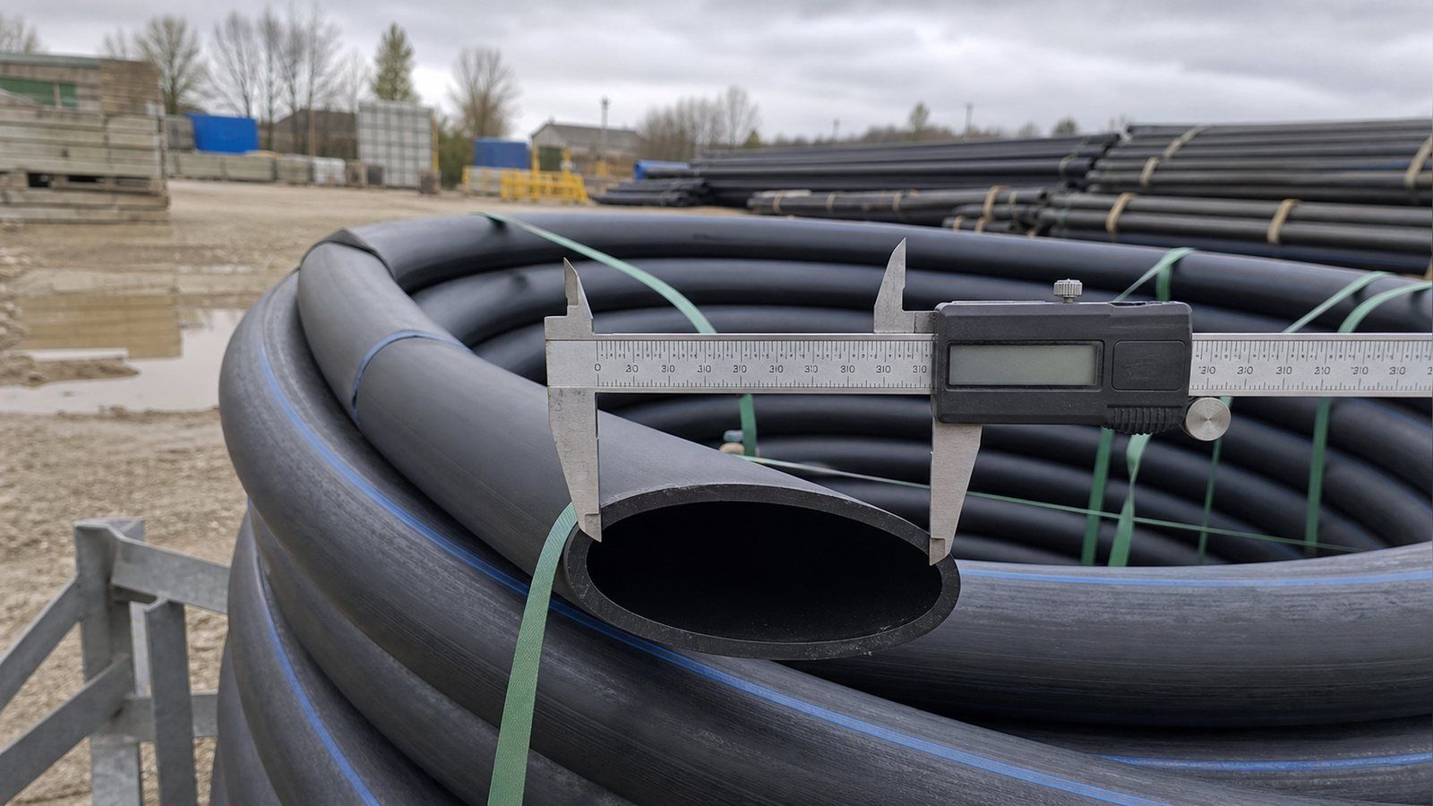
Dos términos describen la misma condición y se confunden constantemente. MAB-1 define la falta de redondez como "la diferencia entre el diámetro máximo medido menos el diámetro mínimo medido" — una longitud, d1 menos d2. La ovalidad es la misma diferencia "expresada como porcentaje", calculada como (d1 − d2) / Dpromedio × 100. Los procedimientos norteamericanos generalmente citan la longitud; los procedimientos métricos y de Australasia generalmente citan el porcentaje. Cuando la hoja de datos de un proveedor y su especificación de proyecto no coinciden, verifique primero si simplemente están usando diferentes unidades para la misma medición.
Los límites de aceptación, en ambos sistemas
MAB-1 da cifras imperiales máximas de falta de redondez junto con un umbral claro para cuándo es necesario el re-redondeo: "La tubería de 2″ IPS / CTS y diámetros menores es lo suficientemente flexible como para que los acoplamientos y las abrazaderas de alineación proporcionen las fuerzas de redondeo necesarias y no se necesite otro dispositivo de re-redondeo", mientras que "para tamaños iguales o mayores a 3″ IPS / DIPS, pueden ser necesarias abrazaderas de re-redondeo a cada lado de un accesorio de electrofusión". PIPA da el equivalente métrico como un porcentaje que varía en DN315: por debajo de eso, la ovalidad en la zona de fusión no debe exceder el 1.5% del DN o 3 mm, lo que sea menor; en DN315 y superior, el 1% del DN o 5 mm, lo que sea menor. Los puntos planos se limitan por separado a 3 mm de profundidad.
| Tamaño de tubería | Falta de redondez máxima (d1 − d2) | Abrazaderas de re-redondeo |
|---|---|---|
| 2″ IPS/CTS y menores | No tabulado; la tubería se flexiona lo suficiente | Generalmente no necesarias |
| 3″ y 4″ | 0.0625″ (1/16″) | Pueden ser necesarias a cada lado |
| 6″, 8″, 10″, 12″ | 0.125″ (1/8″) | Pueden ser necesarias a cada lado |
| Métrico, DN inferior a 315 | 1.5% del DN o 3 mm, lo que sea menor | Deben permanecer durante la soldadura y el enfriamiento |
| Métrico, DN 315 y superior | 1% del DN o 5 mm, lo que sea menor | Deben permanecer durante la soldadura y el enfriamiento |
El momento de las abrazaderas es un detalle que los equipos suelen hacer mal. PIPA establece que "las herramientas de re-redondeo deben permanecer en su lugar durante las fases de soldadura y enfriamiento" — no solo mientras se desliza el accesorio. Si las retira al final del ciclo de fusión, la tubería se relaja hacia su forma ovalada mientras el fundido aún está blando, lo que deshace la razón por la que las colocó.
Los defectos que el re-redondeo no puede corregir
El re-redondeo no es un remedio universal. PIPA señala que "las herramientas de re-redondeo pueden no ser capaces de corregir puntos planos", y cuando la tubería no puede llevarse dentro de los criterios de aceptación, las opciones son recortar "el extremo de la tubería hasta que se elimine el punto plano", reubicar o rotar una silla, o soldar a tope colas de tubería en el extremo.
También existe un defecto que no tiene nada que ver con la redondez: la reversión del extremo del tubo, o convergencia, donde la tensión residual de fabricación tira del extremo hacia adentro y crea una separación que el fundido no puede cerrar. La prueba de PIPA para esto es aritmética que un ingeniero de obra puede realizar con una cinta métrica y una regla: medir DN × 5% desde el extremo del tubo, y en esa posición el diámetro exterior no debe ser menor que el DN. En un tubo de DN500, esto significa medir 25 mm hacia atrás y confirmar que el OD sigue siendo de al menos 500 mm; si no es así, corte en escuadra en ese punto.
La advertencia adjunta a esa prueba es la que cambia la forma en que una cuadrilla planifica su jornada. PIPA advierte que las tensiones residuales permanecen después del corte, por lo que "el tubo recién cortado puede revertir de nuevo, a veces en pocas horas". Preparar una serie de uniones por la mañana para fusionarlas por la tarde no es la eficiencia que parece: los extremos preparados pueden volver a converger antes de que se coloque el accesorio.
El raspado es una dimensión especificada, no un paso de limpieza
El polietileno desarrolla una piel oxidada delgada desde la fabricación y la exposición a los rayos UV, y esa piel no se fusiona. Eliminarla es el paso que decide si la unión funciona, y es donde MAB-1 ubica la gran mayoría de las fallas: la contaminación por una mala preparación de la tubería, los problemas de geometría y los errores de alineación juntos "representan más del 95% de todas las fallas de fusión". No es la calidad del accesorio. No son los ajustes de la máquina. Es la preparación.
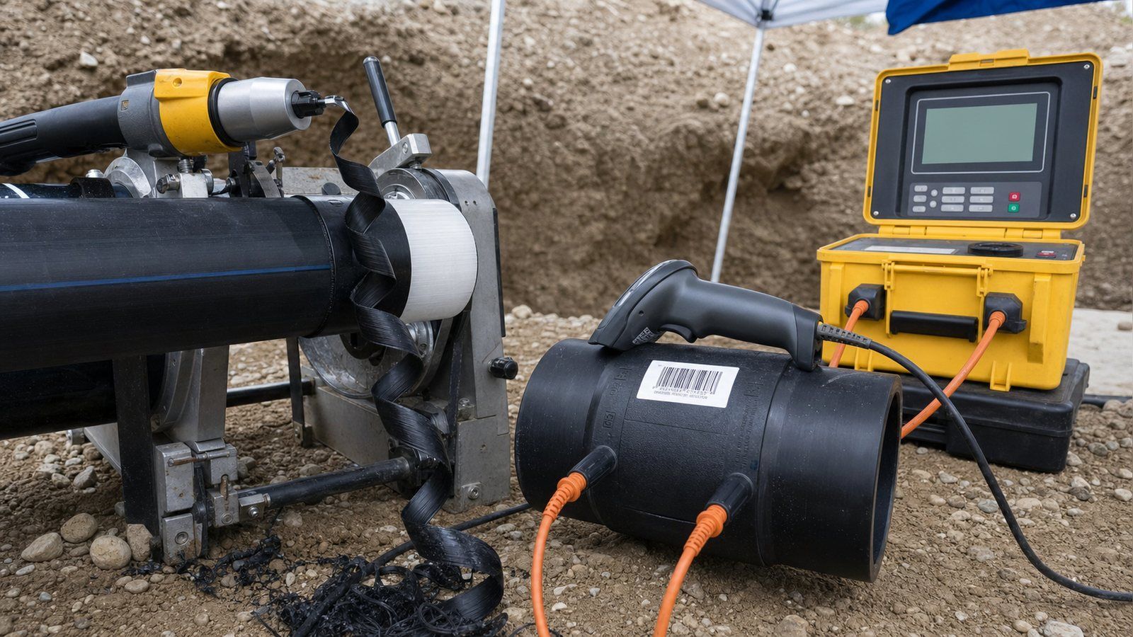
La dimensión es fija y más pequeña de lo que la gente espera. MAB-1 establece que "una cantidad mínima adecuada de material que debe eliminarse es solo siete milésimas de pulgada (0.007″)", un espesor "aproximadamente igual a dos hojas de papel ordinario".
La capa de oxidación no se profundiza significativamente con el tiempo de almacenamiento, por lo que el requisito es el mismo para tubería entregada ayer y para tubería que ha estado en un patio durante dos años: un dato útil para un importador que mantiene existencias.
Lo que casi ninguna página de producto menciona es que también hay un máximo. Raspar no es un caso en el que más sea más seguro: si se elimina demasiado, el diámetro exterior de la tubería disminuye, la separación anular se ensancha y se ha diseñado la misma falla que causa la tubería fuera de redondez. MAB-1 tabula ambos límites por tamaño.
| Tamaño de tubería | Profundidad mínima de pelado | Profundidad máxima total de pelado |
|---|---|---|
| 3/4″ y 1″ | 0.007″ | 0.014″ |
| 1.25″ y 2″ | 0.007″ | 0.017″ |
| 3″ y 4″ | 0.007″ | 0.022″ |
| 6″ a 12″ | 0.007″ | 0.027″ |
La herramienta importa tanto como la profundidad. La norma MAB-1 establece que "el papel de lija, la tela esmeril u otros abrasivos nunca deben utilizarse para preparar la superficie de una tubería para electrofusión", que "las escofinas de madera y las limas metálicas no son herramientas de pelado aceptables", y que los raspadores manuales "no se recomiendan debido a la preparación inconsistente de la superficie".
Los abrasivos pulen los contaminantes dentro de la superficie en lugar de eliminar una capa, y no dejan evidencia de la profundidad alcanzada. Una peladora rotativa produce una viruta continua que el equipo puede medir, que es el objetivo. Si un proveedor o subcontratista propone preparar las uniones con tela abrasiva, eso es motivo para detener el trabajo, no un ahorro de costos.
Dos números más cierran esto. PIPA especifica la longitud de pelado como "la mitad de la longitud del accesorio más 20 mm desde el extremo de la tubería", y la razón de los 20 mm adicionales es una característica de inspección, porque uno de los controles posteriores a la soldadura es que "el pelado sea visible más allá de los extremos del accesorio de electrofusión". Esto convierte un paso invisible en algo que un inspector puede verificar después de realizar la unión.
Y para tuberías dañadas, MAB-1 establece un umbral de reemplazo: "si la muesca supera el 10% del espesor de la pared de la tubería, esa sección debe cortarse y reemplazarse". Las muescas más profundas no pueden eliminarse raspando sin exceder la profundidad máxima de pelado. Si la superficie se recontamina después de la preparación, el remedio especificado es "una concentración mínima del 90% de alcohol isopropílico", y el alcohol desnaturalizado queda explícitamente excluido porque sus aditivos pueden impedir la fusión.
Temperatura, potencia y las condiciones que anulan la unión
La electrofusión tolera mejor el clima que la termofusión por enchufe, que es una de las razones por las que se especifica. No es a prueba de clima, y la ventana operativa es más estrecha de lo que la mayoría de los compradores suponen en ambas direcciones.
La ventana de temperatura
PPI establece el rango de instalación calificado típico en "mínimo 14°F a máximo 113°F", señalando que los fabricantes establecen sus propios límites y algunos son más amplios. PIPA, trabajando en unidades métricas y describiendo la máquina en lugar del accesorio, otorga a las máquinas de electrofusión "límites operativos de temperatura superior e inferior de -10°C a 45°C". Esas dos ventanas son la misma: 14°F es -10°C y 113°F es 45°C. Dos organismos industriales independientes que convergen en límites idénticos es una señal fuerte de que este es un límite físico real, no una exención de responsabilidad conservadora del fabricante.
El extremo caliente afecta a más proyectos que el extremo frío, y la razón es la ganancia solar más que la temperatura del aire. PIPA advierte que las tuberías y accesorios negros bajo luz solar directa "pueden absorber energía solar y alcanzar temperaturas muy superiores a la temperatura ambiente", con "temperaturas superficiales de la tubería de hasta 70°C".
Un día de 32°C en África Occidental o el Golfo está cómodamente dentro de la ventana ambiente mientras la tubería tendida al sol junto a la zanja está 25 grados fuera de ella.
El remedio es la sombra, y PIPA especifica el objetivo: usar protección solar como una carpa portátil "para reducir la temperatura de la superficie de la tubería a 45°C o menos". Para un comprador de proyectos, esto es una partida: el refugio es equipo, no una comodidad opcional, y una cuadrilla sin él se detendrá al mediodía o hará uniones que no deberían haberse hecho.
La humedad es absoluta, no gradual. Las superficies de soldadura deben estar limpias y secas, el ensamblaje debe estar protegido de la lluvia, y la instrucción de PIPA es que "no se debe realizar la soldadura si no se puede proporcionar protección". Las zanjas que acumulan lodo y agua deben desaguarse primero. También hay un mínimo de espacio de trabajo que se diseña fuera de excavaciones estrechas y luego se descubre en obra: "en zanjas, se requiere un espacio libre mínimo de 150 mm alrededor de la tubería", y más a medida que crece el diámetro de la conexión, porque la cuadrilla necesita espacio para operar una peladora, ajustar abrazaderas de recirculación y conectar los cables.
La energía es una decisión de compra, no un detalle de obra
La caja de control debe suministrar una entrada de energía precisa, y la energía inestable es una causa principal de soldaduras fallidas. PPI señala que las cajas de control "están disponibles típicamente en versiones de 110v o 220v" y deben operar "dentro de un rango de frecuencia de 50 a 60 Hertz", lo cual es una trampa real en proyectos de exportación, porque una caja comprada para un mercado puede no coincidir con la flota de generadores en otro. PIPA especifica el suministro más estrictamente: nominal "230V-240V" sin carga, mantenido "estable a 230V±15%" bajo carga, frecuencia estable de 50-60Hz bajo carga, y cables de extensión que "no deben exceder 50m" y deben estar completamente desenrollados.
El dimensionamiento del generador sigue la conexión, y PPI publica las cifras: los enchufes de 1/2 pulgada a 2 pulgadas necesitan un generador mínimo de 2.5 kVA en un disyuntor de 15 amperios, los enchufes de 3 pulgadas a 12 pulgadas necesitan 5 kVA con un disyuntor de 30 amperios a 110v o 20 amperios a 220v, y las abrazaderas de todos los tamaños necesitan 2.5 kVA. Los cables de extensión se especifican por calibre, #10/3 a 25 pies y #8/3 a 50 pies. Una cuadrilla que llega con un generador de 3 kVA para acopladores de 8 pulgadas obtendrá fallas intermitentes que parecen accesorios defectuosos y no lo son.
El tiempo de enfriamiento es cronograma, no holgura
El polietileno es un buen aislante, por lo que la unión permanece blanda mucho después de que cesa la corriente. MAB-1 publica los tiempos de enfriamiento más conservadores entre todos los fabricantes listados, y la lista de cosas que deben esperar es más larga que "presurizar": el tiempo de enfriamiento debe observarse "antes de la remoción de abrazaderas, movimiento, relleno, prueba de presión, golpeteo o puesta en servicio de la conexión". Para acoplamientos de hasta 250 psi, eso es 30 minutos en 3/4 pulgada a 2 pulgadas, 45 minutos en 3 pulgadas a 8 pulgadas, y 60 minutos en 10 pulgadas y 12 pulgadas.
Las derivaciones (saddles) siguen una tabla separada y se clasifican según el tamaño de la salida, no según el diámetro de la tubería principal: 30 minutos para salidas de 3/4 pulgada a 4 pulgadas y 60 minutos para salidas de 6 pulgadas a 12 pulgadas. Por lo tanto, una conexión de servicio de 2 pulgadas en una tubería principal de 12 pulgadas se libera en 30 minutos, una ventaja de programación que vale la pena conocer al planificar un día de empalmes de servicio.
Una precaución sobre las re-soldaduras: si se pierde la energía a mitad del ciclo, algunos fabricantes permiten una re-soldadura una vez que el accesorio se haya enfriado a temperatura ambiente, pero PIPA señala que el tiempo para que un ensamblaje completo baje de 45°C "podría ser de hasta 24 horas dependiendo del tamaño del accesorio y las condiciones ambientales". Eso no es una pausa para almorzar.
El tiempo de enfriamiento es por unión y no se puede comprimir. En un día de acopladores de 8 pulgadas, 45 minutos de tiempo de sujeción sin interrupciones por unión es la restricción real sobre cuántas uniones completa una cuadrilla, no la rapidez con la que pueden raspar.
Qué normas especificar en su orden de compra
Los accesorios de electrofusión se rigen por diferentes normas según lo que transporte la tubería y el mercado al que se destine. Nombrar la correcta es lo que hace que una especificación sea ejecutable; nombrar una retirada le dice a un proveedor que la copió de un documento antiguo.
Para agua, la referencia internacional actual es ISO 4427-3:2019, que cubre accesorios de PE "destinados al transporte de agua para consumo humano, agua cruda antes del tratamiento, drenaje y alcantarillado a presión, sistemas de alcantarillado por vacío y agua para otros fines", para sistemas con una presión máxima de operación permitida de 25 bar a una temperatura de referencia de 20°C. También es el documento que proporciona las definiciones de te de derivación y derivación de ramal utilizadas anteriormente en esta guía. En Europa, el paralelo es EN 12201. La especificación HDPE publicada por IFAN menciona ambos, listando la norma del producto como "ISO 4427 (agua) / EN 12201 (Europa)" con "DIN 8074/8075 para dimensiones y pruebas".
Para gas, tenga cuidado con ISO 8085-3:2001. Es genuinamente la especificación de accesorios de electrofusión de polietileno para "el suministro de combustibles gaseosos", aplicable a accesorios "diseñados para ser unidos por fusión a tuberías de PE que cumplan con ISO 4437" — pero desde entonces ha sido reemplazada por la serie ISO 4437. Citar ISO 8085-3 en una licitación de 2026 no es fatal, aunque un proveedor que se la cite como su conformidad actual está trabajando con una hoja de datos antigua, y eso merece una pregunta de seguimiento sobre qué más en la hoja está desactualizado.
Para cualquier cosa que ingrese a los Estados Unidos, ASTM F1055 es la especificación a nombrar, y hay una razón regulatoria actual para acertar con la edición. PHMSA publicó una regla final directa el 24 de abril de 2026 actualizando la edición incorporada a las regulaciones federales de seguridad de tuberías a "ASTM F1055-16a (Reaprobada 2022) ... aprobada el 1 de noviembre de 2022", reemplazando la edición de 2016, con la incorporación por referencia aprobada "para Sec. 192.283(a); apéndice B de esta parte".
La norma entra en vigor el 1 de enero de 2027, y el cumplimiento después del 23 de junio de 2026 ya está autorizado, por lo que a partir de ahora ambas ediciones están vigentes en diferentes lugares, y una orden de compra que simplemente diga "ASTM F1055" sin especificar la edición es ambigua en el mismo momento en que la referencia está cambiando. La instrucción de selección de MAB-1 es la versión práctica de esto: "todos los accesorios de electrofusión deben estar marcados para indicar que cumplen con los requisitos de diseño y rendimiento de ASTM F1055 antes de ser considerados para su uso".
Los requisitos varían según el mercado, la aplicación y la especificación adoptada por la empresa de servicios públicos, por lo que trate la lista anterior como un punto de partida para una conversación con su autoridad local o ingeniero consultor, en lugar de una respuesta de cumplimiento universal.
Las aprobaciones para agua potable en particular —marcas de certificación como NSF/ANSI 61 o AWWA C906 que MAB-1 menciona como marcas adicionales— son independientes de las normas de producto anteriores y deben confirmarse para el mercado y el producto específicos, no asumirse a partir de una declaración general de conformidad ISO. Para una visión más amplia de cómo encajan estas familias, nuestra guía sobre normas de tubería HDPE cubre el lado de la tubería, y normas de certificación de tuberías cubre lo que significan las marcas en sí.
Un ejemplo de selección: derivación DN110 de una tubería principal PE100
Tomemos un trabajo común: una tubería principal de distribución DN110 PE100 SDR17, ya en servicio, y una nueva derivación de servicio DN63 que debe salir de ella sin interrumpir el suministro. Así es como se resuelven las decisiones anteriores, en el orden en que realmente se toman.
La derivación no puede interrumpir el suministro, por lo que la familia de accesorios se decide primero: se trata de una te de derivación, no de una silla de derivación, porque solo la te de derivación lleva el cortador integrado que permite hacer el agujero después de la fusión en una tubería en servicio. Elegir una silla de derivación aquí para ahorrar coste unitario requeriría despresurizar la tubería principal, que es lo que se quería evitar en el trabajo.
La clase de presión viene después. La tubería principal es PE100 SDR17, que es PN10. La te de derivación debe ser PN10 o superior, porque el sistema toma la clasificación de su componente con la clasificación más baja. Si la única te en stock es PN16, eso está bien y no cuesta nada en rendimiento: la tubería principal sigue rigiendo a PN10. Si la única te en stock es PN8, la conexión de derivación acaba de reducir la clasificación de ese punto de la red por debajo de la tubería a la que está fusionada, y debe rechazarse independientemente del precio.
Luego se mide la tubería, porque el accesorio no perdonará la geometría. DN110 está por debajo del escalón de DN315, por lo que el límite de ovalidad es el menor entre el 1,5% del DN o 3 mm: el 1,5% de 110 es 1,65 mm, por lo que 1,65 mm es el límite.
Utilizando las cifras de trabajo propias de PIPA, una tubería con d1 = 111.0 mm y d2 = 109.5 mm tiene una ovalidad de 1.5 mm, que está dentro del margen permitido de 1.65 mm y pasa. Si hubiera medido 112.0 y 109.5, el resultado de 2.5 mm habría fallado y se necesitaría una abrazadera de re-redondeo en la tubería principal antes de colocar la derivación. En DN110, la tubería puede haber llegado enrollada, lo que hace que esa medición sea más relevante, no menos.
La preparación sigue las dimensiones fijas. Raspe al menos 0.007 pulgadas del área de contacto de la derivación, utilizando una peladora rotativa y nunca un paño abrasivo, y revise la tubería en busca de mellas: cualquier cosa más profunda que el 10% del espesor de pared significa que esa sección se elimina en lugar de rasparse más. Instale el dispositivo de montaje o sujeción del fabricante para esa derivación específica, escanee el código de barras en lugar de introducir los parámetros manualmente para que la caja pueda verificar la resistencia de la bobina y corregir la temperatura ambiente, y confirme que la máquina está alimentada por un suministro que se mantiene dentro de la tolerancia bajo carga.
Finalmente, el programa. La salida es DN63, aproximadamente 2 pulgadas, por lo que la tabla de enfriamiento de la derivación da 30 minutos, vinculados a la salida, no a la tubería principal DN110. Las abrazaderas y cualquier herramienta de re-redondeo permanecen puestas durante todo ese tiempo. Solo después de que hayan transcurrido esos 30 minutos se puede perforar el tee, mover la unión, rellenar o probar la presión. Un equipo, una unión, desde la llegada hasta la derivación perforada, es cómodamente una hora de trabajo, y presupuestarlo como quince minutos porque el ciclo de fusión en sí es corto es cómo se subestima la mano de obra de la electrofusión.
¿Es la electrofusión adecuada para su proyecto?
La electrofusión es un método de unión genuinamente excelente con un conjunto limitado de condiciones en las que es la elección incorrecta. Ser honesto sobre esas condiciones ahorra más dinero que negociar el precio del accesorio.
| Mejor para | No ideal para |
|---|---|
| Reparaciones y empalmes donde ningún extremo de la tubería puede moverse | Tramos largos y rectos de tubería uniforme, donde la fusión a tope es más rápida por unión y no tiene costo de accesorio |
| Conexiones de derivación en tuberías principales que no pueden cerrarse | Sitios sin generador confiable o sin refugio contra la lluvia y el sol |
| Zanjas y pozos congestionados sin espacio para una máquina de fusión a tope | Uniones que deben desmontarse más tarde: la fusión es permanente; use bridas o uniones |
| Redes que mezclan PE80 y PE100, o que mezclan SDR en diferentes fases | Cuadrillas sin operadores capacitados y certificados: la disciplina de preparación es todo el método |
| Proyectos que requieren registros de trazabilidad por unión | Trabajos temporales muy pequeños donde los accesorios de compresión son adecuados y reversibles |
La fila sobre la competencia del operario merece énfasis porque es la que los compradores tienden a subestimar. PIPA afirma que "la mayor contribución individual a una soldadura electrofusión exitosa es la competencia del soldador y su dedicación a la correcta preparación de la superficie y los procedimientos de soldadura", y en Australia esto está formalizado: los instaladores deben estar capacitados y certificados en una unidad de competencia específica y poseer un certificado vigente, recomendando PIPA la reacreditación cada 2-3 años. La mayoría de los mercados no tienen tal requisito, lo que no elimina la dependencia subyacente.
Si está comprando accesorios para un equipo que no ha realizado electrofusión antes, la capacitación es parte del costo del método, y la alternativa es descubrir la estadística del 95% de fallas por preparación en su propio proyecto. Nuestra guía sobre tipos de uniones HDPE presenta las alternativas si esta tabla lo aleja de la fusión.
Qué verificar antes de aceptar un envío de electrofusión
La mayoría de los problemas con los accesorios de electrofusión se pueden detectar en la recepción de mercancías, antes de que lleguen a la zanja. Esta es la secuencia de inspección documentada, extraída de los procedimientos publicados y no de la hoja de marketing de un proveedor.
- Primero, la integridad del empaque: los accesorios deben llegar sellados individualmente en bolsas transparentes dentro de cajas. PIPA es explícito en que el empaque protege la superficie de fusión de la contaminación y la luz solar, y que "el accesorio debe almacenarse en su empaque original hasta inmediatamente antes de su uso". Una caja de accesorios sueltos y sin bolsa es un rechazo, no una negociación de descuento.
- La marcación ASTM F1055: según MAB-1, los accesorios deben estar marcados para demostrar que cumplen con sus requisitos de diseño y rendimiento antes de considerarse para uso. Verifique que la marcación exista en el accesorio, no solo en la factura.
- Formato de código de barras: confirme si la etiqueta lleva el código ISO 13950 de 24 o 32 dígitos, y verifique que los dígitos legibles por humanos estén impresos junto a él. Si su contrato requiere trazabilidad, el formato de 24 dígitos no lo satisfará.
- Rango SDR declarado y clase de presión: ambos deben aparecer en el accesorio o en su etiqueta, junto con el grado de PE. Un accesorio marcado solo como "SDR11" sin grado no ha indicado su clase de presión.
- Condiciones de almacenamiento a la llegada: PIPA especifica almacenamiento bajo techo entre 0°C y 50°C. Para un importador, eso es una especificación de almacén: un contenedor al sol en un muelle puede excederla.
- Herramientas correspondientes: para collares de carga superior, confirme que la herramienta de montaje específica del fabricante esté incluida o ya se posea, y que coincida con la marca realmente enviada, no con la cotizada.
- Documentación del material: solicite el certificado que cubra el envío. IFAN emite un certificado de material por envío en su línea de HDPE, y cualquier proveedor debería poder hacer lo mismo.
Aquí corresponde una advertencia en lugar de una guía de instalación, porque cambia lo que un comprador debe aceptar como evidencia de una buena unión. Los indicadores de fusión se leen ampliamente como una marca de aprobación: suben, la unión es buena. PIPA afirma lo contrario en términos claros: "los indicadores de fusión confirman que se ha desarrollado cierta presión de fusión en la soldadura. No son una confirmación de una soldadura exitosa". Los indicadores pueden subir en una unión realizada sobre una tubería sin raspar u ovalada.
Si el régimen de calidad de un contratista consiste en fotografiar los indicadores levantados, no es un régimen de calidad. Las comprobaciones que tienen peso son el registro de fusión de la caja de control, la ausencia de mensajes de error, que no haya polietileno fundido que haya escapado del casquillo, que no se vean cables calefactores desplazados en el espacio anular, que la marca de profundidad de inserción siga donde empezó, y que se vea la banda raspada más allá de ambos extremos del accesorio.
Conclusión
Seleccionar bien los accesorios de electrofusión de HDPE se reduce a tres preguntas que las rejillas de producto no plantean: ¿qué tiene que hacer esta unión?, ¿cuál es el componente de menor clasificación en ella?, y ¿está la tubería en condiciones geométricas suficientemente buenas para que el fundido cierre el espacio? Si se acierta con estas, la electrofusión ofrece una unión tan resistente como la tubería, en obras donde nada más funcionaría. Si se falla, el accesorio completará su ciclo y levantará sus indicadores sobre una unión que nunca iba a aguantar.
Si está especificando una red de PE en lugar de comprar unas pocas piezas, vale la pena fijar el grado, el SDR y la clase de presión en papel antes de comparar precios de accesorios, ya que el accesorio más barato que reduce la clasificación de su tubería principal es el artículo más caro del pedido. Puede revisar la gama completa de HDPE y sus especificaciones publicadas, o enviar el grado y el programa de tamaños de su proyecto a nuestro departamento de ingeniería y le indicaremos qué podemos suministrar.
Preguntas frecuentes
¿Los accesorios de electrofusión deben coincidir exactamente con el SDR de mi tubería?
No. Los accesorios se asientan en el diámetro exterior, que es constante en todos los SDR, y la mayoría cubren un rango de SDR. Pero el sistema terminado toma la clasificación de presión de su componente de menor clasificación, así que verifique la clase del accesorio contra la de la tubería.
¿Se puede reutilizar un accesorio de electrofusión después de una soldadura fallida?
Solo si se interrumpió la alimentación, y solo según las instrucciones del fabricante. Algunos permiten una re-soldadura después de enfriar a temperatura ambiente; otros requieren que se corte la unión. Los accesorios que fallan por cualquier otra razón se retiran o se abandonan.
¿Cuál es la diferencia entre accesorios de compresión y accesorios de electrofusión?
Los accesorios de compresión se sujetan mecánicamente a la tubería y se pueden desmontar, sin necesidad de energía ni preparación. La electrofusión funde el accesorio y la tubería en una sola parte permanente, requiriendo raspado, abrazaderas, una caja de control y tiempo de enfriamiento.
¿Puede la electrofusión unir tubería de PE80 con tubería de PE100?
Sí. La electrofusión puede unir diferentes grados de PE y diferentes SDR, por lo que es adecuada para redes ampliadas por fases. La sección unida se clasifica entonces según el componente de menor valor.
¿Cuánto tarda en enfriarse una unión por electrofusión?
Para acoplamientos de hasta 250 psi, 30 minutos en tamaños de 3/4 a 2 pulgadas, 45 minutos de 3 a 8 pulgadas y 60 minutos en 10 y 12 pulgadas. Las derivaciones siguen el tamaño de salida: 30 minutos hasta 4 pulgadas, 60 minutos por encima.
¿Necesito una abrazadera de re-redondeo para cada unión por electrofusión?
No. En tamaños de 2 pulgadas IPS/CTS y menores, la tubería generalmente se flexiona lo suficiente para que el acoplamiento y las abrazaderas de alineación la redondeen. Desde 3 pulgadas IPS/DIPS hacia arriba, pueden ser necesarias abrazaderas de re-redondeo a cada lado.
¿Un pasador indicador de fusión elevado es prueba de que la soldadura es buena?
No. Los pasadores elevados confirman que se desarrolló presión de fusión, no que la unión sea sólida. Un pasador puede elevarse sobre tubería sin raspar o fuera de redondez. Utilice el registro de fusión de la caja de control y las inspecciones visuales en su lugar.