
Расчет компенсатора теплового расширения трубопровода: цифры для PPR в жарком климате
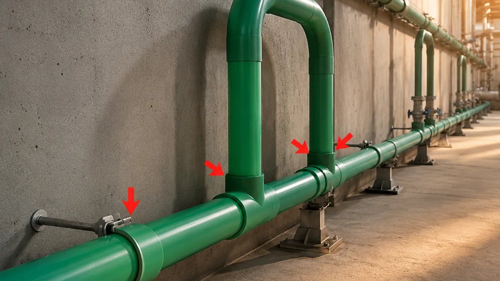
Расчет компенсатора теплового расширения для PPR по опубликованным данным: 0,15 мм/м·К, формула плеча, причины расхождений у производителей в значении константы, а также шаг креплений по DN.
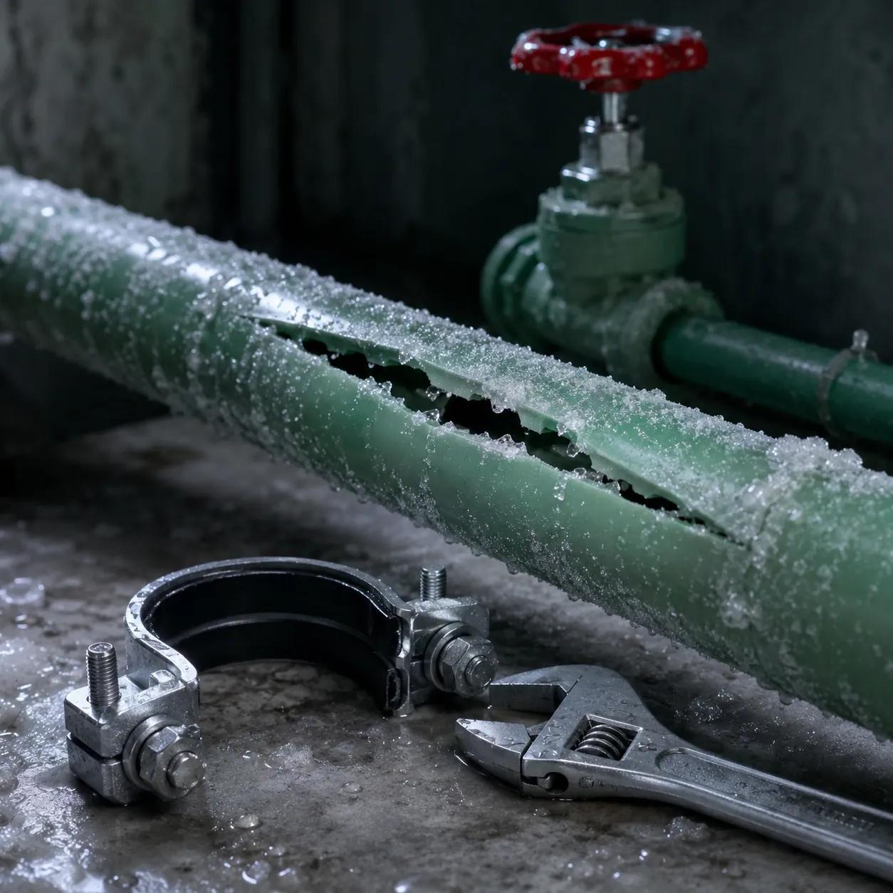
Компенсатор теплового расширения трубопровода — самая дешёвая деталь на чертеже сантехники и самая часто отсутствующая. Соединения, которые выходят из строя через восемь месяцев после сдачи объекта, редко бывают плохо сваренными. Это хорошие сварные швы, несущие нагрузку, которую никто не рассчитал, потому что сорокаметровый прямой участок PP-R вырос на четверть метра между пусконаладкой и первым жарким летом, и единственное место, куда могла уйти эта деформация, — это фитинг.
Вот цифра, с которой начинается каждый такой отказ: однослойный PP-R имеет коэффициент линейного теплового расширения 0,15 мм на метр на кельвин. У меди — 17 × 10⁻⁶ на °C, то есть 0,017. Пластик расширяется в 8,8 раза больше, чем металл, который монтажник устанавливал двадцать лет, и ничто на трубе не говорит ему об этом.
Основные выводы
- Однослойный PP-R расширяется на 0,15 мм/м·К — в 8,8 раза больше, чем медь (0,017), а не в «десять раз», как часто говорят.
- Перемещение рассчитывается по формуле ΔL = α × L × ΔT. Участок длиной 40 м при перепаде температур 40 К смещается на 240 мм — эту цифру можно взять прямо из таблицы Pestan.
- Константа длины плеча — это параметр производителя, а не физическая величина: FV-Plast публикует k = 20, Pestan — K = 15. При одинаковых исходных данных разница для DN63 составляет 615 мм.
- Ширина петли: Lₖ = 2 × ΔL + 150 мм, а FV-Plast добавляет минимум 10 × наружный диаметр.
- Расстояние между клипсами уменьшается с ростом температуры воды: FV-Plast для трубы DN25 PN16 указывает 95 см при 20 °C и 75 см при 80 °C.
- Три производителя публикуют три разных коэффициента для композитных труб — 0,035, 0,05 и лабораторно измеренные 0,085 мм/м·°C. От того, какой из них вы выберете, длина плеча изменится в 2,4 раза.
- Труба, замоноличенная в стену, обычно вообще не требует компенсатора. Штукатурка поглощает перемещение.

Производство композитных труб на IFAN: армирующий слой, меняющий поведение трубы при расширении, встраивается в процессе экструзии, поэтому решение об армировании принимается при заказе, а не на объекте. Нажмите, чтобы посмотреть на YouTube.
Насколько на самом деле удлиняется пластиковый трубопровод
Три независимых руководства производителей дают одинаковую цифру для однослойного PP-R, что само по себе редкость в этой отрасли. Руководство Niron от NUPIGECO указывает αₜ = 0,15 мм/м·К.Технический каталог Pestanуказывает α = 0,15 мм/м·°C.Руководство FV AQUA от FV-Plastуказывает 0,15 для однослойного PP-R и PP-RCT. Одна и та же цифра, три компании, никакой координации.
Сравните с медью. Технический паспорт Lawton Tubeуказывает... придает меди коэффициент 17 × 10⁻⁶ на °C. Разделите 0,15 на 0,017 — получите 8,8. В отраслевой прессе вы встретите фразу «в десять раз больше, чем у меди», и для разговора это достаточно точно, но если вы рассчитываете по нему компенсатор, вы завышаете перемещение на 13% еще до начала расчетов. Используйте 8,8, а лучше — сами коэффициенты.
Единственная нужная формула
Во всех трех руководствах приведено одно и то же выражение, которое NUPIGECO обозначает как формулу B.1:
ΔL = α × L × ΔT — перемещение в мм, где L — длина участка в метрах между двумя неподвижными точками, а ΔT — изменение температуры в кельвинах.
Рассмотрим реальный стояк. Сорок метров однослойного PP-R DN63, смонтированного в день, когда труба находилась при 30 °C, а затем транспортирующего воду с температурой 70 °C. ΔT равно 40. Итак, 0,15 × 40 × 40 = 240 мм. Вам не нужно доверять и этой арифметике — в таблице 38 Pestan есть строка для 40 м и столбец для ΔT 40, и в ячейке указано 240 мм.
Двести сорок миллиметров. Это длина большой отвертки, и ее создает труба, которая выглядит совершенно неподвижной. Если оба конца приварены наглухо к фитингам, которые сами закреплены, это перемещение не исчезает; оно преобразуется в напряжение в стенке трубы и сдвиг в раструбах. Это напряжение добавляется к давлению, которое труба уже несет, поэтому его стоит рассматривать вместе с правилами понижения давления в зависимости от температуры — та же горячая вода одновременно снижает допустимое давление трубы.
| Материал | α (мм/м·К) | Перемещение, 40 м при ΔT 40 К | Опубликовано |
|---|---|---|---|
| Однослойный PP-R | 0,15 | 240 мм | NUPIGECO, Pestan, FV-Plast (все три) |
| Стекловолоконный PP-R, номинально | 0,035 | 56 мм | NUPIGECO; Pestan (как минимум) |
| Многослойный PP-R / PP-RCT | 0,05 | 80 мм | FV-Plast |
| Стекловолоконный PP-R, лабораторные измерения DN25 | 0,085 | 136 мм | Pestan (10% волокна, испытано) |
| Медная труба | 0,017 | 27 мм | Lawton Tube |
| IFAN PP-R и PPR-GF-PPR | — не опубликовано | — необходимо подтверждение завода | IFAN указывает соотношение, а не коэффициент (см. ниже) |
Последняя строка намеренно пуста. IFAN опубликовал заявление об удлинении своей армированной трубы относительно стандартного PP-R, которое рассматривается ниже, но не опубликовал измеренный коэффициент. Заполнение этой ячейки чужим числом сделало бы таблицу более полной, но менее ценной.
Горячий климат: цифра, которую все понимают наоборот
Спросите подрядчика в Аккре или Лагосе, ухудшает ли жаркий климат тепловое расширение, и обычно получите утвердительный ответ. Арифметика говорит нечто более интересное, и правильное понимание этого стоит реальных денег на тендере.
Посмотрите еще раз на ΔT в формуле. Во всех трех руководствах оно определяется одинаково: разница между температурой при монтаже и температурой жидкости, которую будет транспортировать труба. Не максимальная наружная температура. Не расчетная температура окружающей среды. Температура монтажа.
Почему горячая линия становится проще
Европейский монтажник, прокладывающий трубу в неотапливаемом здании при 15 °C и подающий воду 70 °C, проектирует с ΔT 55. Его коллега, сваривающий такую же трубу в здании в Лагосе при 38 °C, проектирует с ΔT 32. На трассе длиной 40 м это 330 мм против 192 мм — в жарком климате на горячих линиях нужно компенсировать на 40% меньше перемещений, просто потому что труба изначально теплее.
Где это бьёт сильнее
Воздействие смещается на холодную сторону, и именно это часто упускают. Охлаждённая вода при 7 °C в здании, где труба закреплена при 38 °C, даёт ΔT 31 в другую сторону. Труба сжимается, и сжатие разрывает соединения, а не вызывает изгиб трассы, поэтому отказ происходит иначе и обычно позже. Стояки систем кондиционирования в высотных зданиях в жарком климате — вот где это проявляется.
- Худший реальный случай: открытый стояк на крыше или снаружи, где труба нагревается солнцем значительно выше температуры воздуха в тени до подачи любой жидкости, а затем в неё подают холодную воду.
- Что даёт изоляция: PP-R имеет теплопроводность 0,24 Вт/м·К, по данным Pestan. Изоляция открытой трассы не меняет α, но сглаживает колебания, которые реально испытывает стенка трубы, поэтому рабочая ΔT снижается.
- Что нужно записать: укажите температуру монтажа в акте пусконаладочных работ. Это исходные данные, на которых строится весь расчёт, и их никто никогда не записывает.
Всё это не означает, что в жарком климате можно пренебречь компенсацией. Это означает, что расчётным случаем часто является линия холодоснабжения и участок, подверженный солнечному воздействию, а не стояк горячей воды, о котором все инстинктивно беспокоятся. Если ваш проектировщик рассчитал все петли исходя из европейских допущений по ΔT, некоторые ваши петли находятся не там, где нужно.
Расчёт компенсационного плеча: константа, о которой никто не говорит, — их собственная
Когда вы знаете величину перемещения, нужно найти место для его компенсации. Это означает участок трубы, идущий перпендикулярно основной трассе и способный свободно изгибаться — плечо на повороте или П-образный компенсатор с двумя такими плечами. Опубликованная формула везде одинакова:
Lₛ = k × √(D × ΔL) — длина плеча в мм, D — наружный диаметр в мм, ΔL — перемещение в мм.
Теперь та часть, которой нет ни в одном результате поиска на первой странице. Эта k — не физическая константа. Это число, которое каждый производитель публикует для своей трубы, и они расходятся. В руководстве FV-Plast прямо указано: "k — материальная константа, k = 20 для PPR". В каталоге Pestan для того же выражения указана константа "для труб Fuidtherm она равна 15".
Пропустим наши 240 мм для DN63 через обе формулы. √(63 × 240) = 122,96. При k = 20 требуется плечо 2 459 мм. При k = 15 — 1 844 мм. Тот же диаметр трубы, то же перемещение, разница 615 мм — и более короткий вариант легче разместить в шахте, именно поэтому кто-то его выберет.
Что с этим делать
Используйте константу, которую публикует ваш поставщик для приобретенной трубы. Если получить ее невозможно, используйте 20 и примите более длинное плечо, поскольку завышенное плечо стоит метра трубы, а заниженное — соединения. Никогда не берите формулу с инженерного блога и не применяйте ее к продукции другого производителя, не проверив, для какого k она была написана.
| Наружный диаметр | ΔL 30 мм | ΔL 50 мм | ΔL 90 мм |
|---|---|---|---|
| DN25 | 0,55 м | 0,71 м | 0,95 м |
| DN40 | 0,69 м | 0,89 м | 1,20 м |
| DN63 | 0,87 м | 1,12 м | 1,50 м |
| DN110 | 1,15 м | 1,48 м | 1,99 м |
Эти цифры — собственная таблица 17 компании FV-Plast, рассчитанная с k = 20. Обратите внимание, что таблица заканчивается на перемещении 90 мм. Наш участок 240 мм далеко выходит за ее пределы, и это руководство вам о чем-то говорит: когда один участок дает такое перемещение, ответ — не один огромный компенсатор. Разбейте участок промежуточной неподвижной опорой и дайте каждому сегменту свой, меньший компенсатор.
Ширина петли и прием, который вдвое сокращает плечо
- Ширина: Lₖ = 2 × ΔL + 150 мм. 150 мм — это защитный зазор; компания Pestan называет его Sₐ и приводит то же значение. FV-Plast добавляет второе условие — ширина также должна быть не менее 10 × наружного диаметра.
- Расчет: при DN63 с перемещением 240 мм: 2 × 240 + 150 = 630 мм, и 10 × 63 = 630 мм. Оба условия дают одну и ту же цифру, что является полезной проверкой того, что вы правильно прочитали столбец диаметров.
- Предварительное растяжение: Компания Pestan публикует Lₛₖ = K × √(d × ΔL) / 2 — растяните компенсатор при монтаже, и вам понадобится вдвое меньшее плечо. Полезно там, где место ограничено.
- Ловушка последовательности: Компания Pestan прямо указывает, что вы формируете петлю, привариваете к ней трубы, затем монтируете, растягиваете и закрепляете ее неподвижными опорами, и только потом продолжаете трассу. Если сначала вварить ее в закрепленную линию, вы деформируете только что выполненные соединения.
Неподвижные опоры и скользящие клипсы: куда направляется перемещение
Компенсатор работает только в том случае, если трубе указано, откуда перемещаться. Это задача двух разных типов клипс, и на большинстве объектов они приходят в одной коробке и устанавливаются взаимозаменяемо.
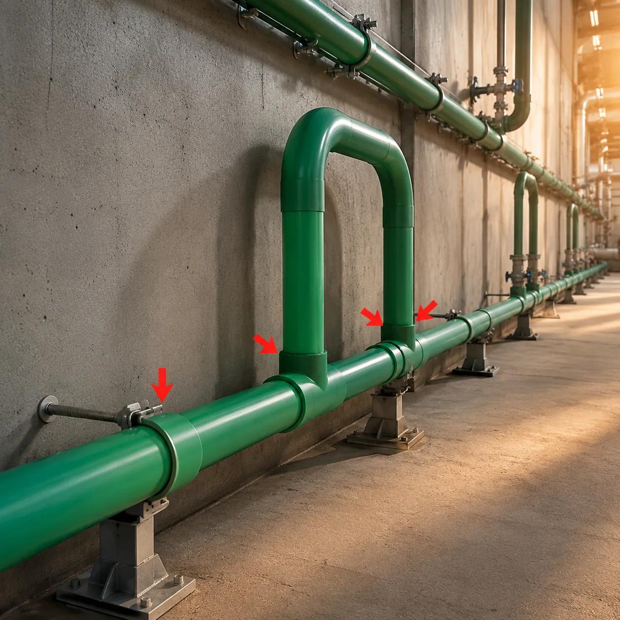
Именно для такого прямого участка применима арифметика. Важно не длина трубы, а расстояние между двумя точками, где она закреплена.
Неподвижная опора захватывает трубу так, что она не может перемещаться вдоль своей оси. Это якорь, определяющий начало и конец участка. Скользящая опора удерживает трубу на линии, но позволяет ей перемещаться вдоль клипсы. Если перепутать их местами, вы получите либо трубу, которой некуда расширяться, либо участок без определенных концов и, следовательно, без рассчитываемого перемещения.Самая распространенная ошибка на объекте тоньше: фитинг становится якорем случайно. Зажмите тройник к стене, потому что так удобно, — и вы создали неподвижную точку, которой нет на чертеже, разделив один проектный участок на два непроектных.Как далеко располагать клипсы
Расстояние между клипсами
Расстояние между клипсами
Расстояние между опорами не является единым числом для каждого диаметра. Оно уменьшается по мере нагрева воды, поскольку теплая труба сильнее провисает между опорами. Таблица 18b FV-Plast для однослойной трубы PN16 на горизонтальных участках:
| Диаметр | 20 °C | 50 °C | 80 °C |
|---|---|---|---|
| DN20 | 90 см | 80 см | 65 см |
| DN25 | 95 см | 90 см | 75 см |
| DN63 | 155 см | 135 см | 115 см |
| DN110 | 200 см | 180 см | 155 см |
Одно предостережение относительно чтения таблиц расстояний между опорами разных производителей. Эквивалентная таблица Pestan индексируется по изменению температуры, а не по температуре воды — в ней для DN25 значения варьируются от 105 см при отсутствии изменения до 60 см при изменении на 70 К. Это разные независимые переменные, и столбцы не совпадают. Чтение одной таблицы с допущениями другой — вот как значение 105 см оказывается на линии, где должны были быть клипсы с шагом 60 см.
Для вертикальных участков FV-Plast умножает свои горизонтальные расстояния на 1.3. И есть одно жесткое правило для стояков, которое ценнее всей таблицы: Pestan предупреждает, что скользящие опоры не должны нести вертикальные линии, поскольку они не рассчитаны на нагрузку в этом направлении и могут перегрузиться и проколоть трубу под весом трубы и воды. Вертикальные линии получают неподвижные опоры.
Расстояние между этими анкерами также публикуется. Таблица 40 Pestan дает расстояние, которое может покрыть один компенсатор между неподвижными точками на однослойном PP-R: 8 м при DN16, 9 м при DN20, 10 м при DN25, 12 м при DN32, 14 м при DN40. Таблица 16 FV-Plast приводит те же пять цифр — а затем для армированной трубы дает 24, 27, 30, 36 и 42 м для тех же диаметров, что в три раза больше и является самым ясным коммерческим аргументом в пользу композитных труб.
Однослойная или стекловолоконная композитная труба: что на самом деле говорят опубликованные цифры
Это решение, которое доходит до вашего заказа, поэтому оно заслуживает честной версии, а не продающей. Армированный PP-R — со стекловолоконным или алюминиевым слоем в стенке трубы — действительно меньше расширяется. Насколько меньше — здесь опубликованные цифры перестают совпадать.
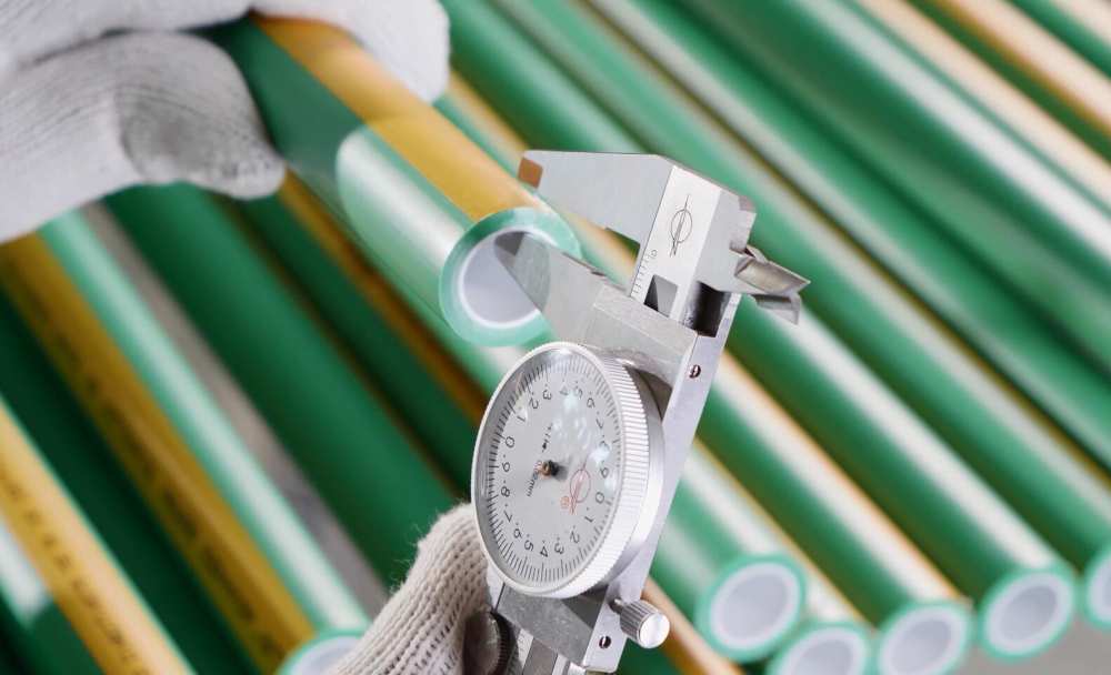
Армирующий слой находится внутри стенки. Снаружи армированная труба и однослойная труба того же диаметра на паллете могут выглядеть почти одинаково, поэтому различие должно контролироваться на бумаге.
Три производителя, три цифры
- 0.035 мм/м·К — таблица B.1 NUPIGECO для PP-R со стекловолокном. Pestan приводит то же значение, но явно как минимум.
- 0.05 мм/м·°C — FV-Plast, для многослойного PP-R и PP-RCT.
- 0.085 мм/м·°C — снова Pestan, на этот раз из лабораторных испытаний трубы DN25 с 10% стекловолокна в центральном слое.
Pestan делает нечто необычно откровенное, публикуя оба значения. Его собственное примечание объясняет, почему они различаются: коэффициент зависит от температуры, длины участка, диаметра трубы, SDR и, прежде всего, от количества стекловолокна в центральном слое. 0.035 — это то, на что способен материал. 0.085 — это то, что показала одна реальная испытанная труба.
Расхождение составляет коэффициент 2,43, и оно напрямую влияет на ваш проект. На участке длиной 40 м при ΔT 40 номинальный показатель прогнозирует 56 мм перемещения, а измеренный — 136 мм. Если вы рассчитаете компенсатор на 56 мм, а установите трубу, которая ведет себя как 136 мм, вы получите компенсатор в два с половиной раза меньше необходимого — это хуже, чем отсутствие компенсатора, потому что чертеж показывает, что проблема решена.
Что IFAN публикует, а что нет
IFAN на своих страницах продукции заявляет, что его армированная стекловолокном труба PPR-GF-PPR «сокращает тепловое расширение до 1/4 от стандартного PPR». Если взять за основу 0,15, то четверть означает примерно 0,0375 — близко к номинальному показателю NUPIGECO и значительно ниже протестированного показателя Pestan. Это соотношение, а не измеренный коэффициент, и данная статья не будет преобразовывать одно в другое. Если вы проектируете с учетом жестких допусков, запросите у любого поставщика, включая IFAN, письменное подтверждение измеренного α для конкретной трубы и содержания волокна, которое вы закупаете.
Каким бы ни был ответ, последствия для закупок одинаковы. Статус армирования — это спецификация, а не сорт того же продукта, и он должен быть отражен в заказе на поставку. Частичная поставка, где половина типоразмеров прибывает армированной, а половина — нет, не является эквивалентной заменой — это два разных коэффициента расширения в одной системе. Наше руководство по смешиванию трубных материалов и допустимым переходам описывает, что происходит в месте их соединения, а полный ассортимент PPR и композитных труб показывает, как линии каталогизируются при консолидации заказа.
- Лучше всего для композитных труб: длинные открытые горизонтальные участки, высокие стояки без места для петель, линии холодной воды в отапливаемых зданиях, везде, где компенсатор физически сложно установить.
- Не стоит использовать: короткие ответвления, любые участки, замоноличенные в стену, и конечные подключения малого диаметра — вы платите за свойство, которое не используется в данной установке.
- В заказе на поставку: укажите тип армирования для каждой позиции и каждого типоразмера. «PPR PN20 DN63» не говорит, армирована ли труба; «PPR-GF-PPR PN20 DN63» — говорит.
Что касается практических аспектов закупок, чтобы спецификация была реализуемой: ассортимент PPR от IFAN охватывает типоразмеры от DN20 до DN160 в классах давления PN12.5–PN25, минимальный заказ — один контейнер с допустимым смешиванием типоразмеров, материал — 100% первичный PP-R 100 с сертификатами на партию, выдаваемыми при каждой отгрузке. Сертификация: DIN 8077/8078, ISO 15874, CE и SGS; SASO, SONCAP или NOM доступны по запросу, если этого требует рынок назначения.
Две вещи, которые данная статья намеренно не упоминает, — это цена и срок поставки. Оба зависят от стоимости смолы, смеси типоразмеров и графика отгрузки, поэтому они указываются под конкретный список типоразмеров, а не публикуются как число, которое устареет к моменту прочтения. И если вам нужен измеренный коэффициент расширения или образец перед принятием решения, запросите его в письменной форме на этапе котировки. Поставщик, который может предоставить его по запросу, говорит вам кое-что полезное о том, насколько хорошо он знает свою собственную экструзию.
Участки, которым компенсатор вообще не нужен
Половина труб в большинстве зданий не требует ничего из вышеперечисленного, и знание того, какая именно половина, предотвращает превращение спецификации в нереализуемую.
Труба, замоноличенная в стену и оштукатуренная, — самый очевидный случай. NUPIGECO называет прокладку внутри стены наиболее рекомендуемым методом для однослойного PP-R, и его обоснование физическое: труба контактирует со штукатуркой, известью и цементом на большой площади, поэтому расширение распределяется внутри трубы, а не передается вдоль нее. Руководство прямо говорит о силе — расширение не создает достаточного усилия, чтобы оторвать плитку или потрескать штукатурку. Pestan говорит то же самое другими словами: при закрытой прокладке окружающий трубу материал поглощает удлинение.
Изолированная труба в штробе ведет себя аналогично: изоляция слегка сжимается, компенсируя перемещение. Два независимых производителя, приходящие к одному выводу, — это практически максимальное подтверждение, которое можно получить по данному вопросу.
Где заканчивается исключение
- Открытые стояки и шахты — ничто не удерживает трубу, поэтому все перемещения свободно распространяются.
- Запотолочные пространства и технические помещения — длинные горизонтальные участки на кронштейнах, классическая зона для компенсационных петель.
- Кровельные и наружные участки — самый широкий диапазон температур на объекте и, как правило, наименее контролируемый.
- Все, что пересекает деформационный шов в конструкции здания, где здание движется независимо от вашей трубы.
Существует также длина, ниже которой арифметика отвечает сама. Подставьте в формулу ответвление 3 м при ΔT 40 — получите 18 мм. Таблица Pestan начинается с 10 м не случайно. Короткие ответвления, конечные подключения и все, что имеет естественное изменение направления, обычно компенсируются за счет обычной гибкости — уже имеющееся колено выполняет работу плеча, которое вы собирались проектировать.
Одно замечание по стандартам, кратко, поскольку их часто переоценивают.ISO 15874-2:2013 — действующий опубликованный стандарт на полипропиленовые трубы для систем горячего и холодного водоснабжения, последний раз пересмотрен и подтвержден в 2023 году, с поправками 2018 и 2022 годов. PP-R от IFAN соответствует ему наряду с DIN 8077/8078, а наше руководство посертификатам PPR и требованиям разных рынков описывает, какие знаки соответствия важны в каждой стране.
Что этот стандартне — это опубликовать коэффициент линейного теплового расширения. Каждое значение α в этой статье взято из технической документации производителя, и только там эти цифры и существуют. Поэтому, если от этой цифры зависит соответствие нормам или гарантия, подтвердите её у поставщика, а для конкретного проекта — у инженера-проектировщика.
Заключение
Тепловое расширение — это единственная нагрузка на пластиковый трубопровод, которую можно полностью рассчитать до прибытия на объект. Четыре параметра определяют её: коэффициент для конкретной трубы, расстояние между неподвижными опорами, разница между монтажной и рабочей температурой и константа плеча, публикуемая производителем. Занесите эти четыре значения в чертёж — и соединения перестанут быть самым слабым звеном системы.
Если вы готовитесь к заказу, полезным следующим шагом будет уточнить статус армирования для каждой позиции трубопровода до подписания коммерческого предложения и запросить у поставщика измеренный коэффициент расширения, а не просто соотношение. Вы быстро поймёте, насколько хорошо поставщик знает свою продукцию.
Часто задаваемые вопросы
Насколько расширяется PPR-труба на метр?
Однослойный PP-R расширяется на 0,15 мм на метр на кельвин — этот показатель одинаково публикуют NUPIGECO, Pestan и FV-Plast. Трубопровод длиной 10 м при перепаде температур 40 K удлинится на 60 мм.
Нужен ли компенсатор для труб, замурованных в стену?
Как правило, нет. Согласно рекомендациям производителей, штробированный и оштукатуренный участок компенсирует собственное расширение за счёт окружающего материала, а возникающее усилие слишком мало, чтобы вызвать трещины в штукатурке или отрыв плитки.
В чём разница между компенсационным плечом и компенсационной петлёй?
Плечо — это один перпендикулярный участок трубы в месте изменения направления. Петля — это П-образная конструкция с четырьмя изгибами, которую применяют, когда прямолинейный участок нельзя развернуть для компенсации расширения.
Каким должно быть расстояние между клипсами для PPR-труб?
Это зависит от диаметра и температуры воды. FV-Plast рекомендует для трубы DN25 PN16 расстояние 95 см при 20 °C и 75 см при 80 °C, а для вертикальных участков расстояние умножается на 1,3.
Действительно ли стекловолоконный PPR расширяется в четыре раза меньше?
Опубликованные значения варьируются от 0,035 до 0,085 мм/м·°C (по данным лабораторных измерений), так что снижение составляет от примерно одной седьмой до примерно половины. Запросите у поставщика измеренное значение для вашего содержания волокна.
Можно ли использовать скользящие опоры на вертикальном стояке?
Нет. Pestan предупреждает, что скользящие опоры не рассчитаны на вертикальную нагрузку и могут перегрузить и повредить трубу под весом трубы и воды. Для стояков применяются жёсткие опоры.