
صمام البوابة مقابل الصمام الكروي: اختلافات التصميم، التحكم في التدفق، واختيار التطبيق
صمام البوابة للعزل؛ الصمام الكروي للتحكم. قارن التصميم، انخفاض الضغط، المعايير (API 600, ASME B16.34)، ومتى تحدد كل نوع.
صمام البوابة مقابل صمام الكرة الأرضية: صمامان بحركة خطية، وظيفتان مختلفتان

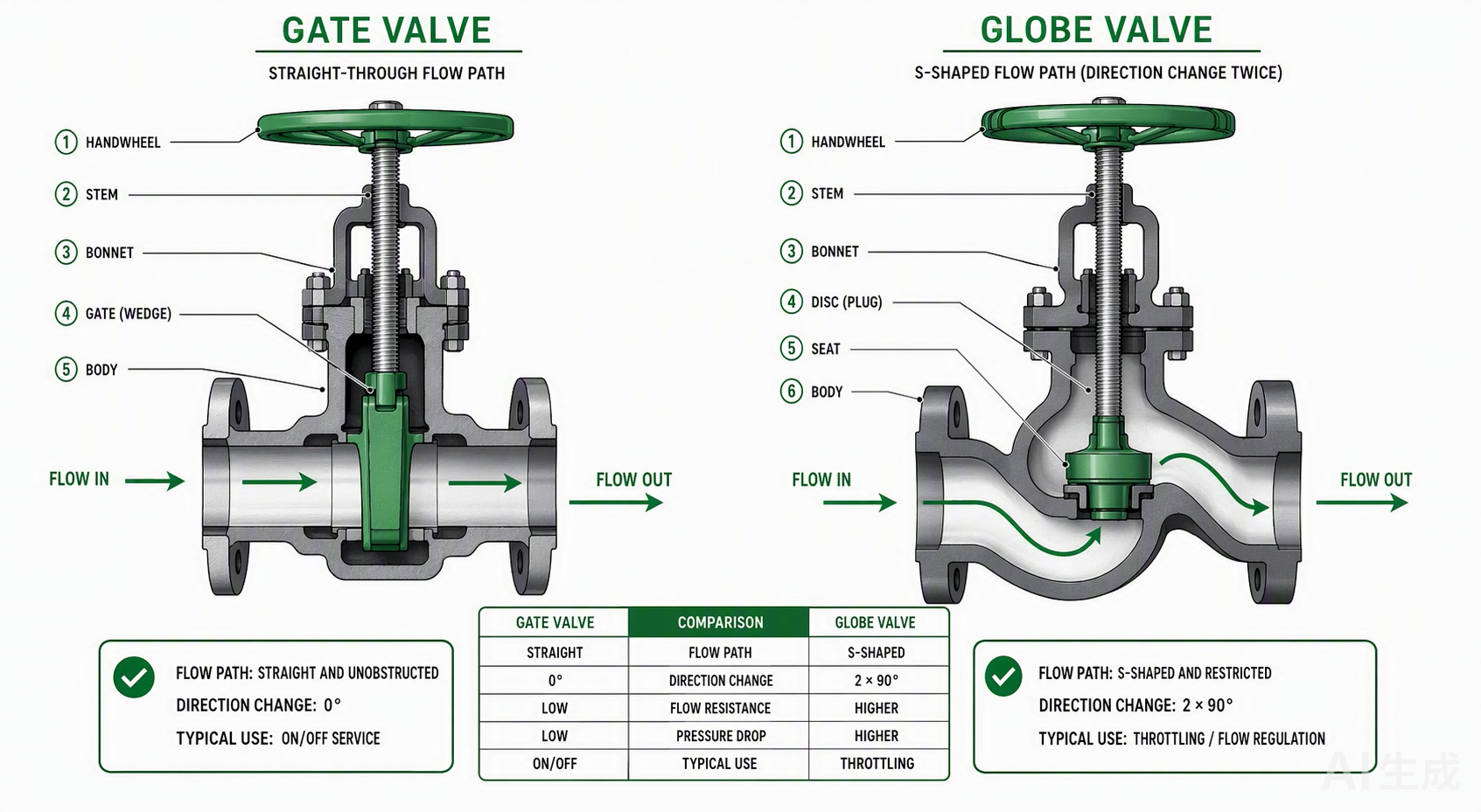
كلا من صمام البوابة وصمام الكرة الأرضية يستخدمان جذعًا متعدد اللفات لتحريك السدادة الداخلية خطيًا. وهنا ينتهي التشابه.صمام البوابة يرفع إسفينًا خارج مسار التدفق ليعطي السائل نفقًا مستقيمًا غير معاق.صمام الكرة الأرضية يدفع قرصًا أو سدادة نحو مقعد ثابت، مما يجبر السائل على المرور عبر مسار التفافي على شكل حرف S يسبب فقدان ضغط دائم حتى عندما يكون الصمام مفتوحًا بالكامل.اختيار النوع الخاطئ يعني إما إهدار طاقة الضخ لسنوات أو تدمير أسطح المقاعد في غضون أسابيع.
المصممون يواجهون هذا القرار باستمرار. نظام الماء المبرد يحتاج صمامات عزل عند كل فرع وصمامات تحكم عند كل ملف. خط البخار يحتاج عزلًا عند الرئيسي وتنظيمًا عند محطة تخفيض الضغط. قد يستخدم نفس المبنى 40 صمام بوابة و15 صمام كرة أرضية، ووضع أحدهما في مكان الآخر خطأ يظهر إما كفقدان ضغط مفرط أو تسرب من المقاعد المتآكلة بعد أشهر فقط.
هذه المقارنة تفصل الاختلافات التصميمية وخصائص التدفق والمعايير الحاكمة وسيناريوهات التطبيق حتى تتمكن من التحديد بثقة بدلاً من العادة. للحصول على نظرة عامة أوسع لأنواع الصمامات الصناعية، راجع دليلنا حولأنواع وصلات الأنابيب.
تصميم صمام البوابة: جذوع صاعدة، بوابات إسفينية، وتدفق كامل التجويف
الجذع الصاعد (OS&Y) مقابل الجذع غير الصاعد
صمامات البوابة تأتي بتكوينين للجذع، والاختيار مهم لكل من سهولة الصيانة وتخطيط المساحة.
تصميمالجذع الصاعد، المعروف أيضًا باسم OS&Y (الجذع الخارجي والنير)، يحرك الجذع عموديًا عند تدوير العجلة اليدوية. الجزء الملولب من الجذع يبقى خارج جسم الصمام، معزولًا عن سائل العملية. وهذا يعطي المشغلين تأكيدًا بصريًا واضحًا لموضع الصمام: إذا كان الجذع مرفوعًا، فالصمام مفتوح. ولأن الخيوط تقع خارج المنطقة المبللة، فإن صمامات البوابة ذات الجذع الصاعد تتعامل مع الوسائط المسببة للتآكل أو التآكل بشكل أفضل من نظيراتها غير الصاعدة.المقايضة:المساحة الرأسية. صمام البوابة ذو الجذع الصاعد على خط 6 بوصات يحتاج إلى خلوص رأسي كافٍ فوق العجلة اليدوية ليتحرك الجذع بارتفاعه الكامل.

تصميمالجذع غير الصاعد (اللولب الداخلي) يبقي الجذع ثابتًا. الجذع ملولب داخليًا في قرص البوابة، لذا فإن تدوير العجلة اليدوية يحرك القرص لأعلى ولأسفل على الجذع الثابت مثل صامولة على برغي. هذا هو الخيار الموفر للمساحة. يناسب الأماكن ذات الخلوص الرأسي المحدود، مثل الغرف تحت الأرض أو غرف الماكينات المزدحمة.العيب: تكون خيوط الساق على اتصال مباشر مع سائل التشغيل، مما يسرع التآكل في الخدمات المسببة للتآكل ويعقد الصيانة.
ملاحظة للمواصفات: بالنسبة لصمامات البوابة النحاسية في تطبيقات السباكة والتدفئة والتهوية وتكييف الهواء، تهيمن تصاميم الساق غير الصاعدة لأنها تناسب التجاويف الجدارية وصناديق الأسقف. تُحجز تصاميم الساق الصاعدة (OS&Y) للأنابيب المكشوفة حيث يتطلب الكود أو تفضيل المشغل إشارة مرئية للموضع. راجع دليلنا الكامل لـ صمامات البوابة لمزيد من التفاصيل حول اختيار الساق.
أنواع الإسفين
العضو المُغلق في صمام البوابة هو إسفين. يوجد نوعان شائعان:
- الإسفين المرن: يحتوي على قطع مركزي يسمح بانحراف زاوي طفيف. يمتص التمدد الحراري ويقلل من التصاق المقعد في الخدمات ذات درجات الحرارة العالية. يُفضل للبخار والسوائل الساخنة.
- الإسفين الصلب: سبيكة صلبة واحدة. أبسط وأكثر متانة، لكنه عرضة للالتصاق الحراري عندما تتسبب تقلبات درجات الحرارة في تمدد تفاضلي بين الإسفين والجسم.
بالنسبة لصمامات البوابة النحاسية في السباكة السكنية والتجارية الخفيفة، تكون الإسفين الصلب قياسية. نادرًا ما يصل نطاق درجات الحرارة في هذه الأنظمة إلى النقطة التي يصبح فيها الالتصاق الحراري مصدر قلق.
تدفق مستقيم بكامل الفتحة
عند الفتح الكامل، يوفر صمام البوابة فتحة غير معوقة. ينتقل السائل في خط مستقيم من المدخل إلى المخرج دون تغييرات في الاتجاه أو تضييقات أو عوائق داخلية. هذه هي الميزة المميزة للتصميم. انخفاض الضغط عبر صمام بوابة مفتوح بالكامل يكون ضئيلًا، وغالبًا ما يكون مهملاً في حسابات الضغط الكلي للنظام.
هذه الهندسة المستقيمة تعني أيضًا أن صمامات البوابة ثنائية الاتجاه. فهي تُغلق في أي اتجاه تدفق، مما يبسط تخطيط الأنابيب عندما قد ينعكس اتجاه التدفق (كما في بعض تكوينات حلقات التدفئة والتهوية وتكييف الهواء).
تصميم صمام الكرة الأرضية: القرص، المقعد، ومسار التدفق على شكل S
كيف يعمل صمام الكرة الأرضية
صمام الكرة الأرضية يحرك قرصًا أو سدادة خطيًا نحو أو بعيدًا عن مقعد حلقي ثابت. يحتوي الجسم على حاجز داخلي — حاجز — يجبر السائل على تغيير الاتجاه مرة واحدة على الأقل قبل الوصول إلى المخرج. هذا يختلف جوهريًا عن صمام البوابة. صمام البوابة إما يقدم فتحة كاملة أو يمنعها. صمام الكرة الأرضية يقيد مسار التدفق عمدًا، وهذا التقييد هو ما يمنحه التحكم في الخنق.

عند فتح صمام الكرة الأرضية بنسبة 20%، تحصل على حوالي 20% من التدفق الكامل. عند فتح صمام البوابة بنسبة 20%، تحصل على تدفق غير مستقر واهتزاز وتآكل متسارع للمقعد. صمام البوابة ليس له نطاق تشغيل مفيد بين الفتح الكامل والإغلاق الكامل. نطاق التشغيل الكامل لصمام الكرة الأرضية مفيد.
أنماط الجسم: النمط T، النمط Y، والزاوية
صمامات الكرة الأرضية تأتي في ثلاثة تكوينات للجسم، كل منها يوازن بين انخفاض الضغط وهندسة التركيب:
- النمط T (جسم Z):التكوين الأكثر شيوعًا. يكون مستوى الجلوس أفقيًا، متمركزًا في الجسم.مسار التدفق:يقوم السائل بعمل منعطفين بزاوية 90 درجة تقريبًا — للأعلى إلى منطقة المقعد، ثم للأسفل نحو المخرج.فقدان الضغط:الأعلى بين جميع أنماط الصمامات الكروية.الأفضل لـ:خنق مياه التبريد، والتحكم العام في العمليات، وخطوط الالتفاف حيث تكون دقة التعديل أكثر أهمية من الضغط المتاح.
- النمط Y:يكون الجذع والمقعد مائلين بزاوية 45 درجة تقريبًا بالنسبة لمسار الأنبوب. يتراجع القرص إلى غطاء مائل يتفرع من التجويف الرئيسي.مسار التدفق:أكثر استقامة ولطفًا بكثير، متجنبًا المنعطفات الحادة بزاوية 90 درجة للنمط T.فقدان الضغط:الأدنى بين أنواع الجسم الثلاثة.الأفضل لـ:خدمة الضغط العالي والسرعة العالية مثل خطوط البخار الرئيسية وخطوط تغذية الغلايات. يسمح محور الجذع المائل أيضًا بالتنظيف والصيانة في الخط دون إزالة الصمام من الأنابيب.
- النمط الزاوي:يكون المدخل والمخرج بزاوية 90 درجة لبعضهما البعض، مما يجمع بين كوع 90 درجة وصمام كروي في جسم واحد.الميزة:يوفر قطعة توصيل.العيب:يقدم نفس تغيير اتجاه التدفق مثل الكوع القياسي.
المقعد والاتجاهية
معظم الصمامات الكروية أحادية الاتجاه.وهي مصممة للتدفق تحت القرص، مما يعني أن السائل يدخل أسفل المقعد ويدفع لأعلى ضد القرص عند الإغلاق. يساعد هذا الاتجاه القرص على الارتفاع عن المقعد بسلاسة عند الفتح ويستخدم ضغط الخط للمساعدة في الإحكام. يشير سهم مصبوب في جسم الصمام إلى اتجاه التدفق المطلوب.تركيب صمام كروي أحادي الاتجاه بالعكسيضر بالإحكام ويمكن أن يمنع الصمام من الإغلاق الكامل.
صمامات البوابة، على النقيض من ذلك، ثنائية الاتجاه.إنها تحكم الإغلاق بشكل جيد في كلا الاتجاهين، مما يبسط التركيب عندما يكون انعكاس التدفق ممكنًا.
خصائص التدفق وفقدان الضغط: المقياس الحاسم
إذا أخذت فرقًا تقنيًا واحدًامن هذه المقارنة، فليكن هذا: هندسة مسار التدفق هي ما يفصل بين هذه الصمامات، وهي تقود كل قرار لاحق حول مكان استخدام كل نوع.

صمام البوابة، مفتوح تمامًا،يعطي السائل نفقًا مستقيمًا.فقدان الضغط:ضئيل.تكاليف الضخ:تبقى منخفضة. يوفر النظام التدفق التصميمي دون مقاومة الصمام.لكن صمام البوابة ليس له نطاق خنق مفيد.عند فتحه جزئيًا، يخلق الإسفين شقًا ضيقًا بين المقاعد. يندفع السائل عالي السرعة عبر هذا الشق ويؤدي إلى تآكل أسطح الجلوس من خلال عملية تسمىسحب السلكتتطور أخاديد على المقاعد. يتوقف الصمام عن الإحكام. يبدأ بتمرير التدفق عندما يجب أن يكون مغلقًا.الإصلاح يعنيإزالة الصمام من الخط وإعادة تشكيل أو استبدال الإسفين وحلقات المقعد.
صمام كروي، مفتوح تمامًا،لا يزال يجبر السائل على المرور عبر مساره على شكل S.فقدان الضغط: دائم وملحوظ مقارنة بصمام البوابة من نفس الحجم. أنت تدفع مقابل هذا الانخفاض في الضغط في طاقة الضخ كل ساعة يعمل فيها النظام. ولكنك تحصل على تحكم خطي ومستقر وقابل للتكرار في الخنق عند أي موضع بين 0% و100% فتح. القرص لا يهتز. المقعد لا يتعرض للتآكل السلكي. يؤدي الصمام وظيفته الأساسية لسنوات دون تدهور.
تحذير: استخدام صمام البوابة كجهاز خنق هو أحد أكثر أخطاء المواصفات شيوعًا وتكلفة في أنظمة السوائل. يمكن أن يظهر ضرر التآكل السلكي في غضون أسابيع في الخدمة عالية السرعة، وغالبًا لا يتم اكتشاف تسرب المقعد الناتج حتى يفشل الصمام في العزل أثناء الإغلاق.
المعايير وتصنيفات الضغط: API 600, API 602, MSS SP-70, ASME B16.34
أربعة معايير تحكم في مواصفات صمامات البوابة والكروي في الممارسة الأمريكية الشمالية. معرفة المعيار الذي ينطبق على فئة الصمام الخاص بك يمنع كلاً من نقص المواصفات والإفراط في المواصفات.
ASME B16.34: إطار الضغط ودرجة الحرارة
ASME B16.34 هو المعيار الرئيسي لتصنيفات الضغط ودرجة الحرارة للصمامات. يغطي الصمامات ذات النهايات الملحومة بالفلنجات أو الملولبة أو الملحومة التناكبية من جميع الأنواع: البوابة، الكروي، الفحص، السدادة، والكرة. يحدد المعيار فئات الضغط من Class 150 إلى Class 4500، مع كون Class 150, 300, 600, 900, 1500, و2500 هي الأكثر شيوعًا في التحديد.
لصمامات الكربون الصلب (مجموعة المواد 1.1، ASTM A216 WCB)، تكون تصنيفات الضغط ودرجة الحرارة عند درجة الحرارة المحيطة (-29 إلى 38 درجة مئوية) هي:
- Class 150: 19.6 بار (285 رطل/بوصة مربعة) عند درجة الحرارة المحيطة، وتنخفض إلى 17.7 بار (256 رطل/بوصة مربعة) عند 100 درجة مئوية، و13.8 بار (200 رطل/بوصة مربعة) عند 200 درجة مئوية.
- Class 300: 51.1 بار (740 رطل/بوصة مربعة) عند درجة الحرارة المحيطة، وتنخفض إلى 46.6 بار (676 رطل/بوصة مربعة) عند 100 درجة مئوية، و43.8 بار (635 رطل/بوصة مربعة) عند 200 درجة مئوية.
- Class 600: 102.1 بار (1,482 رطل/بوصة مربعة) عند درجة الحرارة المحيطة، وتنخفض إلى 93.2 بار (1,352 رطل/بوصة مربعة) عند 100 درجة مئوية.
الكربون الصلب (WCB/A105) لديه درجة حرارة خدمة قصوى تبلغ 425 درجة مئوية (800 درجة فهرنهايت) وفقًا لـ ASME B16.34. بعد ذلك، يجب على المحددين الانتقال إلى سبائك الصلب المنخفضة (ASTM A217 WC6/WC9) أو الفولاذ المقاوم للصدأ الأوستنيتي (ASTM A351 CF8M)، والتي تنتمي إلى مجموعات مواد مختلفة مع منحنيات الضغط ودرجة الحرارة الخاصة بها.
الخلاصة العملية: مع ارتفاع درجة حرارة التشغيل، ينخفض ضغط العمل المسموح به. صمام الكربون الصلب من Class 150 المصنف لـ 285 رطل/بوصة مربعة عند درجة الحرارة المحيطة يمكنه تحمل 200 رطل/بوصة مربعة فقط عند 200 درجة مئوية. إذا قمت بتحديد صمام Class 150 لخط بخار 200 درجة مئوية و250 رطل/بوصة مربعة، فقد حددت أقل من المطلوب. سيكون جسم الصمام مجهدًا بشكل زائد في ظروف التصميم.
API 600 وAPI 602: معايير تصنيع صمامات البوابة
معياران من معايير API يغطيان تصنيع صمامات البوابة الفولاذية، ويختلفان في النطاق:
| المعامل | API 600 | API 602 |
|---|---|---|
| المادة | فولاذ مصبوب | فولاذ مطروق |
| نطاق الحجم | NPS 1 وأكبر | NPS 4 وأصغر |
| وصلات النهاية | ملحومة بفلنجات أو تناكبية | ملولبة أو ملحومة بمقبس |
| التطبيق النموذجي | عزل المصافي والعمليات | عزل الضغط العالي للأنابيب الصغيرة |
| غطاء مانع للضغط | موصى به لـ Class 900+ | لا يُحدد عادةً |
بالنسبة لصمامات الكروي الفولاذية، BS 1873 هو المعيار المرجعي الشائع لصمامات الكروي الفولاذية ذات الفلنجات. اختبار تسرب المقعد وفقًا لـ API 598يستخدم معايير قبول تعتمد على عدد القطرات في الدقيقة، وتختلف حسب حجم الصمام وفئته.ANSI/FCI 70-2 يحدد فئات تسرب المقعد المرقمة من الفئة الأولى إلى السادسة؛ وعادةً ما يفي كلا النوعين من الصمامات بـ الفئة الرابعة (0.01% من سعة التدفق المقدرة) أو أفضل، اعتمادًا على تكوين المقعد.
MSS SP-70: صمامات البوابة من الحديد الزهر
MSS SP-70 يغطي صمامات البوابة من الحديد الرمادي (الحديد الزهر) ذات الوصلات ذات الحواف والملولبة. وينطبق على صمامات البوابة من الحديد الزهر من الفئة 125 والفئة 250 وفقًا لمعيار ASTM A126. هذا هو المعيار الذي يحكم صمامات البوابة من الحديد الزهر ذات القطر الكبير الموجودة في شبكات توزيع المياه البلدية وأنظمة التدفئة والتهوية وتكييف الهواء ذات الضغط المنخفض.صمامات البوابة النحاسية، والتي تمثل التركيز في تطبيقات السباكة والسكنية، عادةً ما تشير إلى المعايير البعدية بدلاً من MSS SP-70، الذي يخص الحديد الرمادي تحديدًا. لمزيد من المعلومات حول تطبيقات الصمامات النحاسية، راجع دليل وصلات الضغط النحاسية.
اختيار التطبيق: العزل مقابل التحكم في التدفق
منطق الاختيار بين صمامات البوابة والصمامات الكروية يتلخص في سؤال واحد: هل يحتاج الصمام إلى تنظيم التدفق، أم يحتاج فقط إلى بدء التدفق وإيقافه؟
متى يتم تحديد صمام بوابة
تنتمي صمامات البوابة إلى مهام العزل. وهي الخيار الصحيح عندما يظل الصمام مفتوحًا بالكامل لأشهر أو سنوات ولا يُغلق إلا أثناء الصيانة أو إيقاف تشغيل النظام. سيناريوهات محددة:
- العزل الرئيسي في حلقات الماء المبرد والماء الساخن: يظل الصمام مفتوحًا أثناء التشغيل العادي.انخفاض الضغط يجب أن يكون في حده الأدنى حتى يوفر النظام التدفق التصميمي دون إهدار طاقة المضخة. الصمام الكروي في هذا الموضع سيضيف مقاومة دائمة وغير ضرورية.
- عزل المعدات عند المضخات والمبردات والغلايات: يحتاج الصمام إلى الإغلاق بإحكام تام للصيانة.الإغلاق ثنائي الاتجاه مهم عندما يكون جانب المعدات قد يحتوي على ضغط متبقٍ بعد إغلاق الصمام.
- عزل الفروع في خطوط الأنابيب الموزعة: يحتاج كل فرع إلى صمام إغلاق لا يضيف فقدًا في الضغط إلى النظام. صمامات البوابة ذات الساق غير الصاعدة تناسب صناديق التفرع وتجويفات الجدران.
- وصلات التنظيف بالبيغ: تسمح الفتحة الكاملة بمرور أجهزة التنظيف دون عوائق. الحاجز الداخلي للصمام الكروي سيمنع مرور البيغ تمامًا.
متى يتم تحديد صمام كروي
تنتمي الصمامات الكروية إلى مهام التحكم في التدفق والتنظيم. وهي الخيار الصحيح عندما يعمل الصمام في أوضاع وسيطة، أو يدور بشكل متكرر، أو يعدل التدفق استجابةً لإشارة تحكم. سيناريوهات محددة:
- التجاوز والموازنة في الملفات: تحتاج ملفات التدفئة والتهوية وتكييف الهواء إلى تنظيم التدفق لمطابقة الحمل. الصمام الكروي عند تجاوز الملف يعدل التدفق بما يتناسب مع الطلب.خاصية التدفق الخطي توفر تحكمًا مستقرًا في أي وضع.
- تنظيم خدمة البخار: تتعامل الصمامات الكروية مع خنق البخار في محطات تخفيض الضغط وخطوط تغذية الغلايات ومصارف خطوط التكثيف.الصمامات الكروية بنمط Y هي المفضلة للبخار عالي الضغط لأن مقعدها المائل يقلل من انخفاض الضغط ويقاوم التكهف.
- خنق مياه التبريد: غالبًا ما تحتاج المبادلات الحرارية في العمليات إلى ضبط التدفق للحفاظ على درجة حرارة المخرج.الصمامات الكروية بنمط Tتوفر دقة التشكيل المطلوبة، ويكون الانخفاض الدائم في الضغط مقبولاً لأن النظام صُمم مع مراعاة ذلك.
- خطوط أخذ العينات والتصريف:تتحكم الصمامات الكروية في معدل التدفق أثناء أخذ العينات لمنع التناثر والتطاير.قصر شوط القرصيسمح بقياس دقيق.
صمام البوابة مقابل صمام الكرة: أيهما يناسب نظامك؟
عند هذه النقطةتكون الصورة الهندسية واضحة. لكن يجب على المختصين أيضًا موازنة عوامل التكلفة والحجم والصيانة لإنهاء الاختيار. إليك الملخص المباشر:
| الخاصية | صمام البوابة | صمام الكرة |
|---|---|---|
| الوظيفة الأساسية | العزل (تشغيل/إيقاف) | الخنق / التنظيم |
| مسار التدفق | مستقيم، بفتحة كاملة | على شكل حرف S، يغير الاتجاه |
| انخفاض الضغط (عند الفتح الكامل) | ضئيل | كبير (فقد دائم) |
| قدرة الخنق | لا شيء (يسبب سحب السلك) | مستقر، خطي عبر النطاق |
| اتجاه التدفق | ثنائي الاتجاه | أحادي الاتجاه (معظم التصاميم) |
| شوط القرص | شوط بوابة كامل الارتفاع | شوط قرص قصير |
| تكرار التشغيل | غير متكرر | متكرر / مستمر |
| التكلفة (الأقطار الكبيرة) | أكثر اقتصادية | أكثر تنافسية من حيث التكلفة (الأحجام الصغيرة) |
| قابلية الإصلاح | صيانة الحشو بشكل أساسي | الأجزاء الداخلية والمقاعد قابلة للوصول |
| المعايير الشائعة | API 600, API 602, MSS SP-70 | BS 1873 |
دليل قرار الاختيار
مرر عبر هذه الأسئلة بالترتيب.أول سؤال تحصل فيه على إجابة "نعم" يخبرك بنوع الصمام الذي يجب تحديده:
- هل يحتاج الصمام إلى تنظيم التدفق؟إذا كانت الإجابة نعم، فحدد صمامًا كرويًا. لا استثناءات. عدم قدرة صمام البوابة على الخنق دون تدمير نفسه ليس قيدًا بسيطًا. إنه قيد تصميمي متجذر في هندسة الإسفين والمقاعد.
- هل الصمام للعزل فقط، وسيظل مفتوحًا بالكامل أثناء التشغيل العادي؟إذا كانت الإجابة نعم، فحدد صمام بوابة. الانخفاض الضئيل في الضغط يوفر طاقة الضخ طوال عمر النظام.
- هل الصمام في مسار تنظيف (pigging)؟إذا كانت الإجابة نعم، فحدد صمام بوابة. الفتحة الكاملة تسمح بمرور أدوات التنظيف. الحاجز الداخلي لصمام الكرة يمنع مرورها.
- هل المساحة الرأسية محدودة (تجاويف الجدران، صناديق الأسقف، الأقبية تحت الأرض)؟إذا كانت الإجابة نعم، فحدد صمام بوابة بساق غير صاعدة للعزل، أو صمام كروي بنمط T للخنق. كلاهما يقلل من المظهر الرأسي.
- هل الخدمة عبارة عن بخار عالي الضغط أو مياه تغذية مراجل؟إذا كانت الإجابة نعم، فحدد صمام كروي بنمط Y. المقعد بزاوية 45 درجة يقلل من انخفاض الضغط ويتعامل مع التدفق عالي السرعة بشكل أفضل من النمط T.
- هل ينعكس اتجاه التدفق أبدًا؟إذا كانت الإجابة نعم، فحدد صمام بوابة. معظم الصمامات الكروية أحادية الاتجاه ولن تغلق ضد التدفق العكسي.
فيديو: شرح أنواع الصمامات
فيديو: نظرة عامة تعليمية على أنواع الصمامات بما في ذلك صمامات البوابة والكرة (يوتيوب)
اختلافات الصيانة وقابلية الإصلاح
يسهل عمومًا صيانة الصمامات الكروية في الخطمقارنة بصمامات البوابة. الأسباب ميكانيكية ومحددة.
الأجزاء الداخلية لصمام الكرة (القرص، حلقة المقعد، والساق) يمكن الوصول إليها من خلال الغطاء. في معظم التصاميم، إزالة مسامير الغطاء ورفع مجموعة الغطاء تمنح الفني وصولاً مباشراً إلى القرص والمقعد. يمكن فحص القرص بحثاً عن التآكل، إعادة تشكيله أو استبداله، ويمكن صقل حلقة المقعد أو استبدالها دون إزالة جسم الصمام من الأنابيب.قصر حركة القرص يعني أن الساق والحشو يقطعان مسافة أقل في كل دورة، مما يطيل عمر الحشو.
تجهيزات صمام البوابة يصعب الوصول إليها أكثر. يتحرك الإسفين عبر الارتفاع الكامل للتجويف. في الصمام ذي الساق الصاعدة، يجب فتح الغطاء ورفع الإسفين عمودياً، مما يتطلب خلوصاً فوق الصمام. في الصمام ذي الساق غير الصاعدة، يكون الإسفين ملولباً على الساق داخلياً؛ ويتطلب استخراجه تفكيك الصمام من الأعلى، وقد تكون خيوط الساق متآكلة أو متقشرة بسبب سنوات من التلامس مع سائل العملية.تلف السحب السلكي في المقاعد يصعب إصلاحه في الموقع بشكل خاص لأن أسطح المقاعد داخل الجسم وقد تتطلب تشغيلاً آلياً.
عملياً، صيانة صمام البوابة تقتصر في الغالب على ضبط الحشو واستبداله.صيانة الصمام الكروي تمتد إلى استبدال كامل للتجهيزات، ولهذا تستفيد الصمامات الكروية المستخدمة في خدمات التحكم النشط من فترات الصيانة المجدولة بدلاً من استراتيجيات التشغيل حتى الفشل.
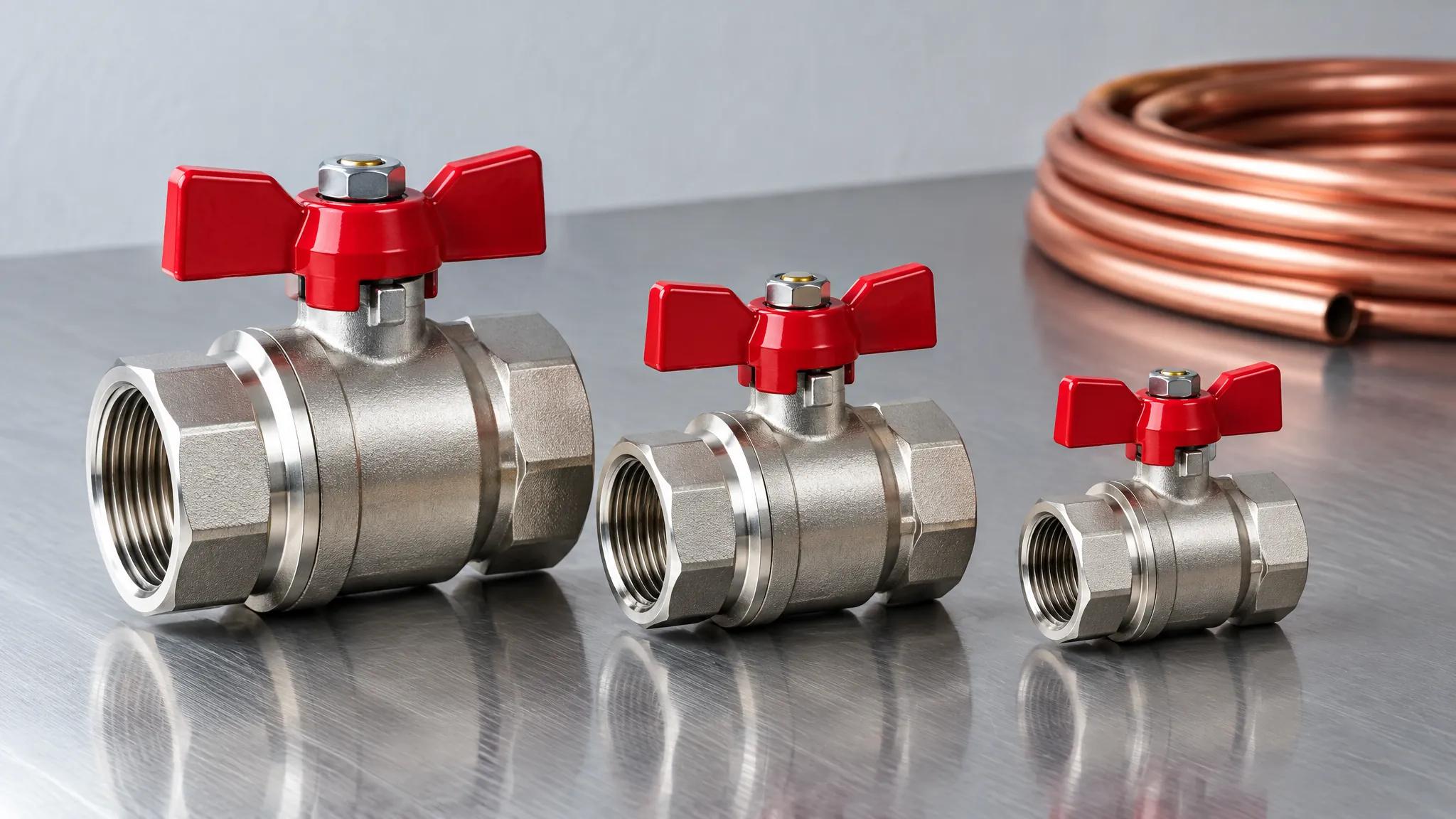
للصمامات النحاسية في أنظمة السباكة والتدفئة والتهوية وتكييف الهواء، يكون حساب التكلفة أبسط. صمامات البوابة النحاسية والصمامات الكروية النحاسية كلاهما غير مكلف نسبياً مقارنة بنظيراتها الفولاذية. عندما يفشل صمام نحاسي، غالباً ما يكون الاستبدال أكثر اقتصاداً من الإصلاح. قرار الإصلاح مقابل الاستبدال يعتمد عادةً على إمكانية الوصول: الصمام في موقع مكشوف قد يستحق إعادة الحشو؛ أما المدفون في تجويف جدار فعادةً ما يُستبدل بالكامل. قدرات التصنيع OEM لدى IFANقدرات التصنيع OEM لدى IFAN تضمن جودة متسقة عبر كلا النوعين من الصمامات.
أخطاء الاختيار الشائعة وعواقبها
ثلاثة أخطاء مسؤولة عن معظم حالات فشل مواصفات الصمامات في أنظمة السباكة والتدفئة والتهوية وتكييف الهواء:
الخطأ 1: استخدام صمام بوابة للخنق
هذا هو الخطأ الأكثر ضرراً والأكثر شيوعاً. المحدد الذي يحتاج إلى تنظيم تدفق عند ملف أو فرع يختار صمام بوابة لأنه أرخص ومتوفر بسهولة أكبر من الصمام الكروي. يتم تركيب الصمام وضبطه على وضع مفتوح جزئياً.
في غضون أسابيع إلى أشهر، اعتماداً على سرعة الخط، يتطور تآكل السحب السلكي على الإسفين والمقاعد. يبدأ الصمام بتمرير التدفق عندما يجب أن يكون مغلقاً. عندما يحتاج النظام إلى عزل للصيانة، لا يمكن للصمام أن يتحمل. يجب تصريف الفرع بأكمله في اتجاه مجرى النهر، مما قد يعني إيقاف تشغيل المعدات التي يخدمها ذلك الفرع.الحل هو استبدال الصمام بصمام كروي، مما يعني إيقاف الخدمة، تعديل الأنابيب، وإعادة التشغيل.
الخطأ 2: تحديد صمام كروي حيث لا يمكن تحمل انخفاض الضغط
هذا هو الخطأ العكسي. يضع المحدد صماماً كروياً على نقطة عزل رئيسية لأنه يريد الصمام "الأفضل".النتيجة:صمام الكرة الأرضية يضيف فقدان ضغط دائم إلى النظام. تعمل المضخات بجهد أكبر. تنخفض معدلات التدفق عند الوحدات الطرفية عن التصميم. قد لا يوفر النظام ما يكفي من التبريد أو التدفئة في نهاية الحلقة.الحلهو إعادة التوازن مع سرعة مضخة أعلى (طاقة أكثر) أو استبدال الصمام بصمام بوابة (تكلفة أكثر).
خطأ 3: تجاهل اتجاه التدفق في صمام الكرة الأرضية أحادي الاتجاه
صمامات الكرة الأرضية المصممة للتدفق تحت القرصيجب تركيبها مع اتجاه التدفق الصحيح. يشير سهم على الجسم إلى ذلك.إذا تم تركيبها بالعكس،قد لا يغلق القرص بشكل صحيح تحت الضغط، وقد لا يحقق الصمام إغلاقًا كاملاً. في خدمة البخار، يمكن أن يتسبب التدفق العكسي عبر صمام الكرة الأرضية في ارتطام القرص بالمقعد، مما قد يتلف المشغلات.
تكلفة أي من هذه الأخطاءدائمًا أعلى من تكلفة تحديد الصمام الصحيح في البداية. صمام الكرة الأرضية أغلى من صمام البوابة بنفس الحجم، ولكن استبدال صمام بوابة متآكل، وتفريغ النظام، وتركيب صمام الكرة الأرضية الذي كان يجب تحديده من البداية يكلف 5 إلى 10 مرات أكثر من فرق السعر الأصلي.
الاختلافات الرئيسية في لمحة
للرجوع السريعأثناء مراجعة المواصفات، إليك الحقائق الأساسية:
- صمامات البوابةتستخدم بوابة إسفينية ترفع خارج مسار التدفق، مما يوفر تدفقًا مستقيمًا وكامل التجويف مع فقدان ضغط ضئيل. وهي ثنائية الاتجاه ومناسبة لواجب العزل فقط.الفتح الجزئييسبب تآكلًا بالسحب السلكي. تصميمات الساق الصاعدة (OS&Y) تعطي مؤشرًا بصريًا للموضع؛ تصميمات الساق غير الصاعدة توفر مساحة الرأس.قارن صمامات البوابة مع الصمامات الكرويةلمزيد من السياق.
- صمامات الكرة الأرضيةتستخدم قرصًا أو سدادة تتحرك نحو مقعد ثابت، مما يجبر السائل على مسار على شكل S مع فقدان ضغط دائم. وهي عادة أحادية الاتجاه ومناسبة للخنق والتنظيم.أجسام النمط Tلديها أعلى فقدان ضغط؛أجسام النمط Yتقلل من ذلك بإمالة المقعد حوالي 45 درجة.
- المعايير: API 600يحكم صمامات البوابة الفولاذية المصبوبة (NPS 1+، ذات حواف/ملحومة بعقب).API 602يحكم صمامات البوابة المدمجة من الفولاذ المطاوع (NPS 4 وأصغر، ملولبة/ملحومة بمقبس).MSS SP-70يغطي صمامات البوابة من الحديد الزهر الرمادي (ذات حواف/ملولبة، Class 125/250).ASME B16.34يوفر تصنيفات الضغط ودرجة الحرارة لجميع أنواع الصمامات من Class 150 إلى Class 4500. يغطي BS 1873 صمامات الكرة الأرضية الفولاذية ذات الحواف.
- تصنيفات الضغط:ASME B16.34 Class 150 كربون فولاذي (WCB) مصنف عند 19.6 بار (285 رطل لكل بوصة مربعة) عند درجة حرارة محيطة. Class 300 مصنف عند 51.1 بار (740 رطل لكل بوصة مربعة). ينخفض كلا التصنيفين مع ارتفاع درجة الحرارة، مع حد أقصى للكربون الفولاذي عند 425 درجة مئوية (800 درجة فهرنهايت).
- الصيانة:صمامات الكرة الأرضية أسهل في الإصلاح في الخط لأن المشغلات يمكن الوصول إليها من خلال الغطاء. صمامات البوابة أصعب في الخدمة لأن الإسفين والمقاعد عميقة داخل الجسم. في ممارسة الصمامات النحاسية، غالبًا ما يكون الاستبدال أكثر اقتصادا من الإصلاح.
- التكلفة:تعتبر صمامات البوابة أكثر اقتصادية في الأقطار الكبيرة. بينما تكون صمامات الكرة الأرضية أكثر تنافسية من حيث التكلفة في الأحجام الصغيرة الموجهة للتحكم. يتقلص فرق السعر كلما قل حجم الصمام.
عندما تحدد مواصفات صمام، فأنت لا تختار مجرد مكوّن. بل تحدد الأداء الطاقي، وسهولة الصيانة، وموثوقية ذلك الفرع من الأنابيب طوال عمر المبنى. التصميم المستقيم لصمام البوابة و المسار المتعرج لصمام الكرة الأرضية ليسا مجرد ميزات تصميمية عرضية. بل هما السبب الهندسي الذي يجعل كل نوع من الصمامات يتفوق في مهمته المحددة ويفشل في مهمة الآخر. إذا أتقنت هذا التمييز في مرحلة التحديد، فسيؤدي النظام أداءً مصممًا له لعقود.
هل تبحث عن مورد موثوق لأنابيب ووصلات PPR أو حلول صمامات متكاملة؟ استكشف مجموعة منتجات IFAN الكاملة لصمامات البوابة النحاسية، وصمامات الكرة الأرضية، وأنظمة الأنابيب الشاملة المصنعة وفقًا للمعايير الدولية.