
Балансировка контуров тёплого пола: настройка каждого расходомера
Балансировка коллектора тёплого пола — это арифметика, а не догадки. Расчёт расхода каждого контура в л/мин по формуле Q = m x cp x dT, разобранный на реальном примере с шестью контурами.
Стяжка была уложена в марте. Котёл подобран, насос работает, каждый привод открывается, когда его термостат даёт сигнал — а в задней спальне клиента 17 °C, в то время как в никому не нужном коридоре некомфортно тепло. Монтажник увеличивает температуру на термостате спальни. Ничего не происходит, потому что термостат не может заставить воду течь туда, куда она уже не идёт.
В этом объекте нет проблемы с теплом. Это проблема распределения, и решение — набор цифр, которые должны были быть определены до того, как трубу закрепили: целевой расход в литрах в минуту для каждого контура на коллекторе.
Почти все руководства по балансировке тёплого пола скажут вам, что эти цифры обычно находятся в диапазоне от 1 до 3 литров в минуту. Это правда, но бесполезно, потому что это среднее значение по чужим домам. Ни одно из них не показывает, как получить цифру для вашей комнаты — расчёт, который превращает тепловую нагрузку в ваттах в показания расходомера. В этой статье этот расчёт расписан полностью, проверен по опубликованной производителем таблице пусконаладки, а затем применён к полному коллектору с шестью контурами при двух разных расчётных условиях.
- Расход контура определяется одним уравнением: Q = m × cp × ΔT, преобразованным для получения литров в минуту. Всё остальное на этой странице — применение этого уравнения.
- Расчётная дельта T обычно составляет около 10 K для котла и 5 K для теплового насоса. Уменьшение ΔT вдвое удваивает требуемый расход каждого контура — тот же дом, то же тепло, но вдвое больше воды.
- Выведенное из первых принципов, это уравнение воспроизводит все девять значений из опубликованной производителем таблицы расходов контуров с точностью до 3,5 %. Эти таблицы — не ноу-хау; это тот же расчёт с уже округлёнными значениями.
- EN 1264-3:2021 — это то, по чему вы проектируете (расчёт); EN 1264-4:2021 — то, по чему вы монтируете и сдаёте в эксплуатацию. Оба стандарта опубликованы 31 мая 2021 года.
- Поддержание длины контуров в пределах примерно 10–15 % друг от друга — это практика, которой стоит следовать, но она не спасёт комнату, которой нужна высокая мощность через короткий контур, и приведённый ниже пример показывает именно такой случай.
Что на самом деле исправляет балансировка: один насос, шесть контуров, разное сопротивление
Коллектор — это параллельная цепь. Один насос подаёт воду в подающую гребёнку, вода распределяется между подключёнными контурами и снова собирается в обратной гребёнке. Ничто в этой схеме не гарантирует равномерного распределения.
Вода распределяется между параллельными контурами обратно пропорционально их сопротивлению, а сопротивление контура растет с его длиной. Поэтому контур в коридоре длиной 26 м и контур в гостиной длиной 92 м, подключенные к одному коллектору, не получают одинаковые расходы — короткий забирает гораздо больше своей доли, а длинный остается без воды. В коридоре перегрев. В гостиной температура никогда не достигает заданного значения. Обе неисправности имеют одну причину.
Именно поэтому повышение температуры на термостате не может это исправить. Термостат лишь решает, открыт ли его привод; он не имеет власти над тем, сколько воды от насоса пройдет через конкретный порт, когда он открыт. Если контур гидравлически обделен, его открытие на более длительное время лишь продлевает это состояние.
Два регулятора и какой из них вы на самом деле используете
Почти каждый современный коллектор дает вам два устройства на контур, и они не взаимозаменяемы:
- Расходомер (ротаметр) на подающей гребенке — поплавок в градуированной трубке, который одновременно показывает и задает литры в минуту, проходящие через этот контур. Это балансировочное устройство. Именно его вы поворачиваете.
- Обратный клапан на обратной гребенке — порт, на котором установлен термопривод и который получает команду вкл/выкл от комнатного термостата. Это управляющее устройство, а не балансировочное.
Путаница между ними — самый распространенный способ, которым коллектор оказывается «сбалансированным» путем дросселирования обратных клапанов, что приводит к системе, которая работает до тех пор, пока приводы не начинают циклировать, и настройки тихо перестают что-либо значить.
Какой стандарт регулирует какое решение
Две части одной серии европейских стандартов охватывают эту работу, и их смешение заставляет людей искать правила проектирования в монтажном документе.
| Стандарт | Название | Что он определяет для вас |
|---|---|---|
| BS EN 1264-3:2021 опубликован 31 мая 2021 г. |
Водяные напольные системы отопления и охлаждения — Расчет | Проектная сторона: как система рассчитывается и подбирается по размерам, включая потери давления. Именно отсюда берутся значения расхода. |
| BS EN 1264-4:2021 опубликован 31 мая 2021 г. |
Водяные напольные системы отопления и охлаждения — Монтаж | Строительная сторона: требования к проектированию и конструкции напольной структуры, а также процедура испытания на герметичность. |
Одна деталь из редакции 2021 года важна, если вы работаете по более старому методу расчета. По сравнению с изданием 2009 года, EN 1264-3:2021 добавил четыре новых подпункта о потерях давления — 4.1.3.1, 4.2.3.1, 4.3.3.1 и 5.2.1.1 — поэтому гидравлическое сопротивление теперь рассматривается более явно в текущей базе расчета, чем раньше. Если ваш справочный материал предшествует этой редакции, то подход к потерям давления, который он дает, является более старым. Обе части опубликованы BSI как британские стандарты; запись в каталоге для части 3 содержит полную историю изменений.
Уравнение, лежащее в основе каждой таблицы расходов контура
Вот и вся суть. Контур должен отдавать определенное количество ватт в помещение, и он делает это, приходя теплым и уходя более холодным. Сколько воды ему нужно, зависит от того, насколько ему позволено остыть по пути.
Q = m × cp × ΔT
Q = тепловая мощность (кВт) · m = массовый расход (кг/с) · cp = удельная теплоемкость воды (кДж/кг·К) · ΔT = перепад температур между подачей и обраткой (К)
Q вам известно, так как это теплопотребность помещения. ΔT вы выбираете, так как он определяется источником тепла. Таким образом, преобразуем формулу для неизвестной величины:
m = Q / (cp × ΔT)
Это дает килограммы в секунду. Расходомер показывает литры в минуту, поэтому делим на плотность, чтобы получить кубические метры в секунду, затем умножаем на 60 000, чтобы получить литры в минуту.
Две константы и почему о них можно не беспокоиться
Обе константы зависят от температуры, что вызывает очевидный вопрос: при какой температуре их принимать? Честный ответ: для данной цели это практически не имеет значения, и стоит понять почему, а не просто принять на веру.
| Температура воды | cp (кДж/кг·К) | Плотность (кг/м³) |
|---|---|---|
| 20 °C | 4.1834 | 998.30 |
| 40 °C (типичная подача теплого пола) | 4.1789 | 992.30 |
| 50 °C | 4.1809 | 988.12 |
| 60 °C | 4.1845 | 983.28 |
Во всем диапазоне, в котором когда-либо будет работать система теплого пола, cp изменяется на 0,14 % — это практически константа, и использование 4.1789 кДж/кг·К везде дает погрешность, значительно меньшую, чем уже заложенная в расчет теплопотерь. Плотность снижается сильнее — на 0,60 % между 20 °C и 40 °C, поэтому считать один литр за один килограмм — это упрощение, а не тождество. При наладочной точности, когда вы считываете показания поплавкового расходомера на глаз по печатной шкале, это вполне допустимое упрощение. Но стоит знать, что это именно упрощение.являетсятаковым.
Расчет одной строкой
Собрав все преобразования вместе, получаем формулу, которую можно запомнить:
Расход (л/мин) = Q(Вт) ÷ (4.1789 × ΔT) ÷ 992.30 × 60
Пример: ванная комната с теплопотребностью 1400 Вт при ΔT 5 К. 1.4 кВт ÷ (4.1789 × 5) = 0.0670 кг/с. Делим на 992.30 → 0.0000675 м³/с. Умножаем на 60 000 → 4.05 л/мин.
Доказательство правильности уравнения: воспроизведение заводской таблицы наладки
Формула в статье сама по себе мало что значит. Поэтому вот тест, который может повторить каждый.
В руководстве Uponor Underfloor Heating Installation Guide на странице 51 приведена таблица наладки с расчетным расходом для контура в зависимости от длины контура и тепловой мощности пола. Она представлена как справочная — без вывода, без объяснений, просто цифры, которым монтажник должен доверять. В другом месте того же документа, на странице 33, компания указывает расчетную основу своих таблиц: ΔT 7.5 °C, труба 16 мм с шагом 200 мм.
Этого достаточно, чтобы проверить арифметику. Труба с шагом 200 мм означает, что один метр трубы обслуживает 0.2 м² пола, поэтому обслуживаемая площадь контура равна его длине × 0.2. Умножьте на мощность в Вт/м², чтобы получить ватты контура, затем примените уравнение при ΔT 7.5 К.
| Длина контура | Мощность пола | Расчет здесь | Uponor стр. 51 | Разница |
|---|---|---|---|---|
| 50 м | 50 Вт/м² | 0.96 л/мин | 1.0 л/мин | −3.5 % |
| 50 м | 70 Вт/м² | 1,35 л/мин | 1,4 л/мин | −3,5 % |
| 50 м | 100 Вт/м² | 1,93 л/мин | 2,0 л/мин | −3,5 % |
| 75 м | 50 Вт/м² | 1,45 л/мин | 1,5 л/мин | −3,5 % |
| 75 м | 70 Вт/м² | 2,03 л/мин | 2,1 л/мин | −3,5 % |
| 75 м | 100 Вт/м² | 2,89 л/мин | 3,0 л/мин | −3,5 % |
| 100 м | 50 Вт/м² | 1,93 л/мин | 2,0 л/мин | −3,5 % |
| 100 м | 70 Вт/м² | 2,70 л/мин | 2,8 л/мин | −3,5 % |
| 120 м | 50 Вт/м² | 2,32 л/мин | 2,4 л/мин | −3,5 % |
Девять значений из девяти — каждое на 3,5 % ниже опубликованной цифры, и обратите внимание, что это одно и то же 3,5 % каждый раз, а не разброс. Постоянное смещение в девяти независимых строках — признак намеренного запаса, а не накопленной ошибки: производитель округляет вверх — в безопасную сторону, потому что контур с чуть большим расходом незаметно недогревает, а контур с чуть меньшим расходом оставляет комнату холодной.
Вывод важнее упражнения. Эти опубликованные таблицы — не ноу-хау, это данное уравнение с уже применённым округлением и заложенными допущениями. А значит, как только ваша задача отличается от допущений таблицы — другой ΔT, другое расстояние между трубами, помещение с тепловой нагрузкой не 50, 70 или 100 Вт/м² — таблица перестаёт работать, а уравнение продолжает работать.
Пример расчёта шестипетлевого коллектора с балансировкой при 5 K и 10 K
Вот полный пример. Шесть петель на одном коллекторе, реальные тепловые нагрузки, реальные длины петель. Всё в двух правых колонках — это уравнение из предыдущего раздела, ничего не взято из таблиц.
| Петля | Тепловая нагрузка | Длина петли | Расход при ΔT 10 K (котёл) |
Расход при ΔT 5 K (тепловой насос) |
|---|---|---|---|---|
| Гостиная A | 1 200 Вт | 46 м | 1,74 л/мин | 3,47 л/мин |
| Гостиная B | 1 200 Вт | 46 м | 1,74 л/мин | 3,47 л/мин |
| Кухня-столовая | 1 750 Вт | 68 м | 2,53 л/мин | 5,06 л/мин |
| Спальня 1 | 1 150 Вт | 45 м | 1,66 л/мин | 3,33 л/мин |
| Спальня 2 | 980 Вт | 38 м | 1,42 л/мин | 2,84 л/мин |
| Ванная | 1 400 Вт | 42 м | 2,03 л/мин | 4,05 л/мин |
| Итого по коллектору | 7 680 Вт | 285 м | 11,11 л/мин 0,667 м³/ч | 22,22 л/мин 1,333 м³/ч |
О чём говорят две колонки
Тот же дом. Те же 7 680 Вт. Насос должен перемещать ровно вдвое больше воды в правой колонке, чем в левой, и это самый важный факт на этой странице.
Расчётная ΔT определяется источником тепла, а от него зависит и труба, которую вы выбираете для его транспортировки — этот вопрос мы подробнее рассматриваем в нашем сравнении PE-RT и PEX для тёплого пола. Система с котлом обычно проектируется на 10 K — подача 50 °C, обратка 40 °C — тогда как тепловой насос обычно проектируется на 5 K, подача 40 °C и обратка 35 °C, потому что меньший перепад позволяет машине работать при более низкой температуре подачи и лучшем коэффициенте производительности. Это общепринятые проектные значения, а не требования какого-либо стандарта, и стоит отметить, что разобранная выше таблица производителя находится между ними — 7,5 K.
Последствие, однако, совсем не обычное: замена котла на тепловой насос на существующем коллекторе удваивает потребность в расходе на каждом контуре. Циркуляционный насос, который комфортно работал при 0,667 м³/ч, теперь должен обеспечивать 1,333 м³/ч при более высоком сопротивлении, поскольку перепад давления растет примерно пропорционально квадрату расхода. Модернизации здесь регулярно проваливаются, и провал выглядит точно так же, как в вступительном абзаце — одни комнаты в порядке, дальние холодные.
Контур, который не спасает никакое эмпирическое правило
Теперь посмотрим на ванную и разделим расход каждого контура на его длину, чтобы увидеть, насколько интенсивно работает каждый метр трубы:
| Контур | Расход на метр контура при ΔT 5 K |
|---|---|
| Гостиная A / B | 75,5 мл/мин |
| Кухня-столовая | 74,5 мл/мин |
| Спальня 1 | 74,0 мл/мин |
| Спальня 2 | 74,6 мл/мин |
| Ванная | 96,5 мл/мин |
Пять контуров плотно группируются вокруг 75 мл/мин на метр. Ванная на 29 % выше всех — ей требуется самый большой расход среди всех помещений, кроме кухни, при этом она подается через один из более коротких контуров, потому что ванные комнаты имеют высокие теплопотери и более высокую целевую температуру пола на малой площади.
Это тот случай, с которым популярный совет не справляется. «Держите длину контуров в пределах 10–15 % друг от друга» — это здравый совет, и он подробно рассматривается в следующем разделе, но это правило о длине, а проблема ванной — в ваттах на квадратный метр. Ее контур уже имеет разумную длину. Удлинение его для соответствия другим только ухудшит ситуацию, потому что вы добавите сопротивление контуру, который и так требует наибольшего расхода.
Что ванной действительно нужно, так это чтобы на этапе проектирования ее признали гидравлически требовательным контуром и обработали соответственно: держать короткой, близко к коллектору и обеспечить необходимый напор насоса. Если вы обнаружите это только при пусконаладке, ваши возможности сузятся до насоса.
Настройка расходомеров без погони за собственными регулировками
Имея на руках таблицу расходов, физическая работа проста — при условии, что она выполняется в правильном порядке. Именно порядок избавляет вас от погони за регулировками по коллектору в течение полдня.
- Заполните, удалите воздух и запустите насос, прежде чем что-либо трогать. Воздух в контуре отображается как низкий расход и заставит вас регулировать клапан, чтобы исправить проблему, которая не является гидравлической.
- Полностью закройте все расходомеры. Все, прежде чем начать. Частично открытый коллектор не дает вам точки отсчета.
- Закройте все обратные клапаны — снимите термоприводы и установите ручные колпачки, чтобы контуры были под вашим контролем, а не под контролем термостата.
- Откройте обратный клапан одного контура, затем откройте его расходомер от полностью закрытого до тех пор, пока он не покажет целевое значение для этого контура. При работающей системе и насосах.
- Повторите для каждого контура, затем пройдитесь по кругу еще раз.Второй проход не обязателен — см. ниже.
- Установите обратно стопорные кольца, затем приводы.Правильно установленное стопорное кольцо означает, что счетчик вообще не будет вращаться, что предотвращает дрейф настроек в дальнейшем.
- Запишите все итоговые значения на этикетке коллектора.Иначе следующий человек, который откроет этот шкаф, не сможет узнать проектные расходы.
Почему второй проход обязателен
Контуры на общем коллекторе гидравлически связаны. Откройте контур 4 — и вы измените давление, доступное контурам 1, 2 и 3 — расход, который вы тщательно выставили на контуре 1, не будет фактическим расходом контура 1, когда весь коллектор открыт. Uponor прямо заявляет об этом в той же главе о пусконаладке: повторите процесс для каждого контура, затем вернитесь и выполните точную настройку, потому что каждый контур будет взаимно влиять на другие.
На практике один полный проход плюс один проход точной настройки достаточен для шестиконтурного коллектора. Пропуск второго прохода — самая частая причина, по которой коллектор, который был «сбалансирован», все еще имеет холодную комнату.
Когда регулятор достигает предела
Расходомер имеет ограниченный ход. На расходомере Uponor topmeter три полных оборота от закрытого положения — это полностью открыто, и дальнейшая регулировка невозможна — и у каждого поплавкового расходомера есть аналогичный предел. Это превращает досадную мелочь в полезный диагностический признак.
Если контур полностью открыт, все остальные контуры настроены правильно, а целевой расход все еще не достигается, проблема не в контуре. Вы исчерпали гидравлический авторитет, и ответ находится выше по потоку: скорость насоса или проект, требующий от этого контура больше, чем может дать насос. Рекомендации Uponor говорят то же самое — если верхний расходомер или запорный клапан полностью открыты, а проектный расход не достигнут, может потребоваться регулировка скорости насоса.
Существует связанный предел, о котором стоит знать до проектирования, а не после — и этот предел подвижен, поэтому он часто застает врасплох. Поплавковые расходомеры не имеют единой шкалы. Расходомер Uponor TM рассчитан на «установку и визуальную индикацию (0–6 л/мин)», в то время как сменные верхние расходомеры широко продаются на 0–5 л/мин, а на бюджетных коллекторах распространены устройства на 0–4 л/мин. Ничто на коллекторе не подскажет вам, какой у вас, пока вы не прочитаете напечатанную шкалу.
Это превращает рабочий график в две разные задачи. При ΔT 5 K контур кухни требует 5,06 л/мин: это читается на верхнем расходомере 0–6 с запасом около 15 % шкалы, и просто невозможно установить на расходомере 0–5 или 0–4. Тот же график можно реализовать на одном коллекторе и невозможно на другом, и разница заключается в спецификации компонента, которую никто не проверяет на стадии проектирования.
Таблицы самого производителя демонстрируют дисциплину — переработанная таблица для 16 мм ранее показывает максимум 3,0 л/мин, и даже более высокая таблица Uponor для 20 мм достигает пика 4,6 л/мин для петли 80 м при 100 Вт/м², что все еще находится в пределах диапазона собственного расходомера. Проверьте шкалу на вашем конкретном коллекторе до того, как будет зафиксирован график петель. Петля, которую вы не можете считать, — это петля, которую вы не можете сбалансировать.
Разделка трубы PEX под латунный компрессионный фитинг — соединение на каждом порту коллектора. Видео: IFAN Group.
Проектирование длин петель так, чтобы коллектор можно было сбалансировать в принципе
Все вышесказанное предполагает, что график петель поддается балансировке. Многие — нет, и это решается на бумаге задолго до того, как кто-то возьмется за отвертку.
Правило примерно равных длин и что оно вам дает на самом деле
Отраслевое эмпирическое правило — держать петли на одном коллекторе в пределах примерно 10–15 % друг от друга по длине. Когда длины близки, петли имеют схожее сопротивление, поток распределяется почти равномерно сам по себе, и балансировочные клапаны выполняют очень небольшую работу — некоторые проектировщики оставляют ручные балансировочные клапаны практически полностью открытыми, когда длины находятся в пределах примерно 10 %.
Относитесь к этому как к практике проектирования, а не как к требованию какого-либо стандарта. Механизм, стоящий за этим, реален, и именно от него вам следует отталкиваться: чем шире разброс сопротивлений, тем сильнее каждый клапан должен дросселировать, и тем больше напора насоса намеренно теряется, чтобы заставить неравномерную систему работать. Коллектор с петлями от 22 м до 92 м технически можно сбалансировать. Но это навсегда приводит к постоянным потерям энергии насоса и не оставляет запаса при изменениях.
Предел для каждой отдельной петли
Диаметр трубы ограничивает площадь пола, которую может обслуживать один порт, поскольку более длинная петля при заданном расходе означает большее падение давления. Опубликованные таблицы подбора от известных производителей устанавливают максимальную длину петли в диапазоне 80–120 м в зависимости от диаметра трубы и тепловой мощности системы — таблицы подбора Uponor содержат строки 75 / 100 / 120 м для PEX 20 × 2 мм и строки 80 / 100 / 120 м для многослойной трубы 16 × 2 мм и PEX 15 × 1,5 мм, а в руководстве по проектированию компании указано 100 м как максимум для 16 мм и 80 м для 12 мм, включая подводки к коллектору и от него.
Этот последний пункт часто упускают из виду. Помещение, находящееся в 15 м от коллектора, тратит 30 м своего лимита длины петли только на подвод и обратку, прежде чем хотя бы один метр будет уложен в пол. Мы более подробно рассматриваем вопрос выбора диаметра трубы в нашем руководстве по выбору трубы для теплого пола, а соотношения размеров и номинального давления — в статье размеры труб PEX.
Разделение помещения и как это влияет на ваш заказ
Когда помещение превышает предельную длину, разделите его на два порта, а не создавайте один длинный контур с высоким сопротивлением. Именно поэтому в приведенном графике гостиная показана как две петли по 46 м вместо одной петли 92 м — и именно в этот момент проектирование петель превращается в решение о закупке.
Подсчитывайте порты по схеме контуров, а не по количеству комнат. Шесть комнат в этом примере дают шесть контуров только потому, что гостиная поглотила один порт, который не понадобился ванной; другая планировка даст другой ответ. Коллекторные блоки доступны в продаже от 2 до 12 выходов, причем модульные типы собираются из секций на 2, 3 и 4 порта, соединяемых резьбой, вплоть до максимума в 12 выходов, так что практическое ограничение обычно заключается в том, что вы должны решить до заказа, а не в том, что оборудование не может вас вместить. Если вы выбираете между типами и материалами коллекторов, наш гид по коллекторам PEX охватывает эту сторону; сами бухты и фитинги находятся в нашем каталоге продукции.
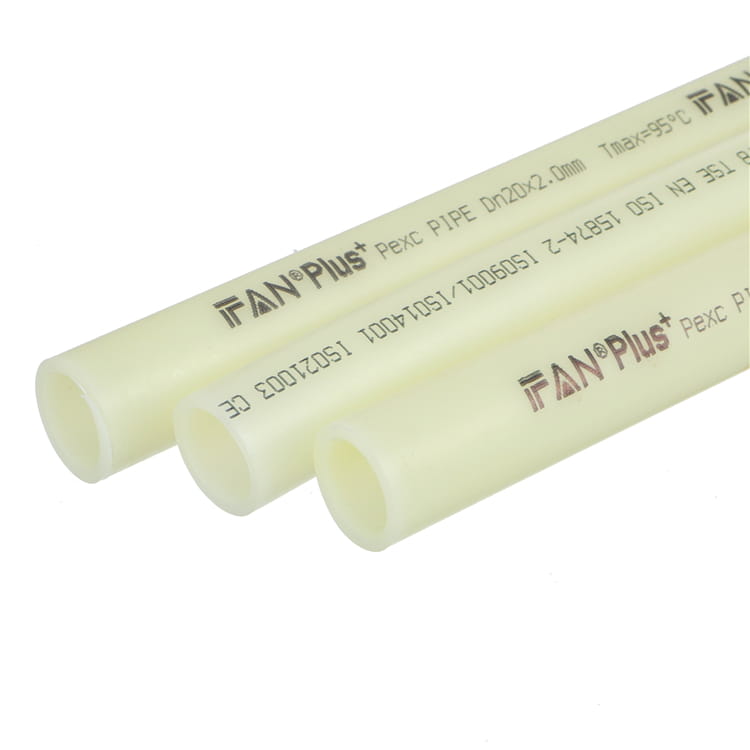
Перед укладкой стяжки
Короткий список, потому что все, что в нем, невозможно исправить после:
- Длины контуров, записанные для каждого порта, измеренные по бухте, а не оцененные по площади пола.
- Целевой расход, рассчитанный для каждого контура, при ΔT, с которым будет работать ваш реальный источник тепла — а не при обобщенном значении.
- Каждая целевая величина в пределах диапазона измерения расходомера. Если нет — меняется проект, а не наладка.
- Помещения с высокой тепловой нагрузкой определены — ванные комнаты и помещения с большим остеклением — и сделаны короткими и близкими к коллектору.
- Испытание на герметичность проведено по EN 1264-4 до стяжки, поскольку этот стандарт содержит процедуру монтажа и испытания на герметичность. Запросите у поставщика бухт протокол испытаний партии, покрывающий бухту, которую вы собираетесь залить, а на проекте, достаточно крупном, чтобы это оправдать, закажите образец бухты до основной поставки, чтобы фитинги и переходники коллектора были проверены на фактической трубе до монтажа.
Контрольный список решений
Балансировка — это не навык. Это график чисел, составленный до монтажа и подтвержденный при наладке, и арифметика за ним умещается в одну строку.
- Какова тепловая нагрузка каждого помещения в ваттах?Без этого ничего больше нельзя рассчитать — и ни одна цифра расхода, взятая из таблицы, не будет верна для вашего здания.
- С каким ΔT реально будет работать источник тепла?Около 10 K для котла, около 5 K для теплового насоса. Ошибётесь здесь — и все значения расхода будут неверны в два раза.
- Расход на контур = Q ÷ (4.1789 × ΔT) ÷ 992.30 × 60.Литры в минуту на контур, записанные.
- Все ли значения находятся в пределах диапазона расходомера?Если нет, разделите контур или пересмотрите ΔT, прежде чем заказывать что-либо.
- Находятся ли длины контуров в пределах примерно 10–15 %?Если одно помещение требует длинного контура, разделите его на два порта.
- Какой контур является гидравлически самым сложным?Обычно это помещение с наибольшей нагрузкой Вт/м², а не самый длинный контур. Держите его коротким и близко к коллектору.
- Был ли коллектор отбалансирован вторым проходом?Один проход — это не балансировка коллектора.
Самая полезная привычка — записать схему расходов и оставить её у коллектора. Сбалансированная система без записи — это одно изменение термостата от несбалансированной системы, которую никто не сможет диагностировать.
Часто задаваемые вопросы
Какой расход должен быть у каждого контура тёплого пола?
Универсальной цифры не существует — она зависит от тепловой нагрузки помещения и вашего расчётного ΔT. Рассчитайте: расход в л/мин = ватты ÷ (4.1789 × ΔT) ÷ 992.30 × 60. Большинство бытовых контуров попадают в диапазон 1–3 л/мин при ΔT котла и примерно вдвое больше при тепловом насосе.
Почему одно помещение остаётся холодным после балансировки коллектора?
Проверяйте в таком порядке: воздух в контуре, делали ли вы второй проход балансировки, и полностью ли открыт расходомер этого контура. Если он полностью открыт и всё ещё не достигает целевого значения, проблема в напоре насоса или в проекте, а не в клапане.
Какой ΔT должен быть у тёплого пола?
Расчётная практика — около 10 K для котельных систем и около 5 K для тепловых насосов, где меньший перепад повышает эффективность машины. Проектные таблицы производителей часто находятся между ними, около 7.5 K.
Должны ли контуры тёплого пола быть одинаковой длины?
Не обязательно одинаковыми, но поддержание их в пределах примерно 10–15 % значительно упрощает балансировку, поскольку контуры имеют схожее сопротивление. Если помещение требует слишком длинного контура, разделите его на два порта коллектора.
Какой стандарт охватывает проектирование и балансировку тёплого пола?
EN 1264-3:2021 охватывает расчёт — проектную часть, включая потери давления. EN 1264-4:2021 охватывает монтаж и процедуру испытания на герметичность. Оба были опубликованы 31 мая 2021 года.
Сколько контуров может быть на одном коллекторе?
Коллекторные блоки обычно доступны от 2 до 12 выходов, с модульными рядами, состоящими из секций на 2, 3 и 4 порта. Определяйте количество портов исходя из вашей схемы контуров, а не из количества помещений — разделённые помещения занимают дополнительные порты.