
Mezcla de materiales de tubería: qué transiciones se mantienen y qué pedir
Mezcla de PPR, PVC, HDPE y metal: por qué las roscas R ISO 7-1 sellan y las roscas G ISO 228-1 no, dónde divergen las bridas PN10 y PN16, y qué pedir.
Mezclar materiales de tubería en un mismo sistema no es el problema que la mayoría de los compradores creen. Cualquier edificio, sin importar su antigüedad, ya utiliza tres o cuatro materiales a la vez: una columna de acero galvanizado que alimenta ramales de PP-R, un desagüe de PVC bajo un tramo de cobre, una línea de servicio de HDPE que llega a un conjunto de medidor de latón. Los sistemas que presentan fugas casi nunca son los que tienen varios materiales. Son aquellos donde alguien unió dos materiales con una pieza que no pertenecía a ninguno.
Esa distinción tiene un costo asociado. Cuando una transición roscada gotea seis semanas después de la puesta en marcha, el diagnóstico habitual es "accesorio defectuoso" y la respuesta habitual es comprar la misma pieza incorrecta a un proveedor diferente. La causa real suele ser que la pieza sellaba en una cara cuando la pieza de acoplamiento esperaba sellar en la rosca, una diferencia escrita en dos normas ISO separadas, impresa en ninguna página de catálogo e invisible hasta que el sistema está bajo presión.
Conclusiones clave
- La unión es el componente que falla, no la tubería. Especifique la unión antes de especificar el material.
- Las roscas ISO 7-1 (R, Rc) sellan en la propia rosca. Las roscas ISO 228-1 (G) no: sellan en una cara, e ISO 7-1 establece claramente que una rosca exterior paralela no es una rosca de unión.
- MIL-STD-889D, emitido el 21 de julio de 2021, eliminó el método de diferencia de voltaje para metales disímiles. La compatibilidad ahora es una tasa de corrosión: por encima de 0.009 mil/año, un par es incompatible y necesita protección.
- Las bridas EN 1092-1 PN10 y PN16 comparten un patrón de pernos en DN150 y divergen por encima de este. En DN200 ambas usan un círculo de pernos de 295 mm, pero PN10 tiene 8 agujeros y PN16 tiene 12.
- El PP-R se mueve 0.15 mm por metro por kelvin; el PE se mueve 0.20. Un cambio de material es un punto de anclaje no planificado a menos que diseñe para la diferencia.
- Una línea de transición necesita seis campos en la orden de compra. La mayoría de los catálogos, incluido el nuestro, imprimen menos que eso: confirme el estándar de rosca por escrito antes de que se cargue el contenedor.

Las mitades metálica y plástica de un accesorio de transición se fabrican con diferentes procesos en la misma planta: forjado en frío para el latón, moldeo por inyección para el cuerpo de polímero. Video: IFAN Group.
Mezclar materiales de tubería es normal: mezclar métodos de unión es lo que falla
Pregunte a un proveedor si puede mezclar materiales de tubería en un mismo sistema y generalmente obtendrá un sí con un encogimiento de hombros. Esa respuesta es correcta e inútil. La pregunta útil es más específica: en el punto donde el material A termina y el material B comienza, ¿cuál de las reglas de los dos sistemas gobierna la unión? Porque ambos tienen reglas, y no son las mismas.
Las normas mismas están construidas de esta manera. ISO 15874, la familia de normas para sistemas de polipropileno para agua caliente y fría, se divide en partes: tuberías en la Parte 2, accesorios en la Parte 3, y luego incluye una Parte 5 separada para la aptitud para el uso del sistema. Esa última parte existe porque una tubería conforme unida a un accesorio conforme puede producir un ensamblaje no conforme. La edición de 2013 fue revisada y confirmada en 2023, por lo que esto es pensamiento actual, no histórico.
ISO 4427-1:2019, que cubre polietileno para suministro de agua y drenaje presurizado, es aún más explícita. Su alcance establece que se aplica a tuberías y accesorios de PE, sus uniones, y a uniones con componentes hechos de PE y otros materiales. La norma anticipa que su sistema de PE encontrará algo que no es PE, y se niega a fingir lo contrario. Establece una presión máxima de operación permitida de hasta 25 bar a una temperatura de referencia de 20 °C.
Cuatro familias de uniones cubren casi todos los casos
En lugar de memorizar una matriz de pares de materiales, clasifique cada unión que especificará en una de cuatro familias. La familia determina qué puede salir mal, qué norma la rige y qué debe aparecer en el pedido.
| Familia de unión | Uso típico | Qué determina el éxito |
|---|---|---|
| Roscada | Plástico a latón, latón a acero, medidores, válvulas, grifos | ¿A qué estándar de rosca se cortaron ambas mitades? |
| Embridado | Bombas, válvulas grandes, tuberías principales de HDPE, DN50 y superiores | Coincidencia del círculo de pernos, número de agujeros y cara de junta |
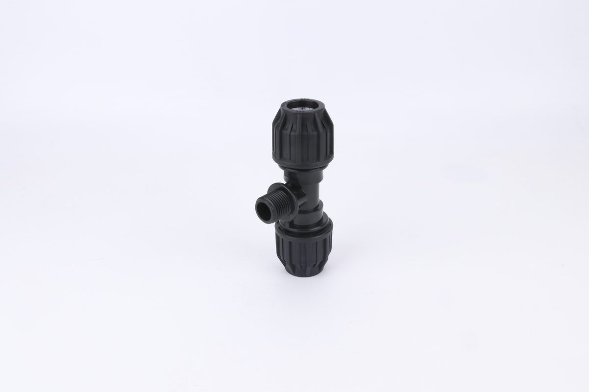
| Compresión / mecánico | Líneas de servicio de PE, reparaciones, trabajo enterrado, diámetros exteriores diferentes | Rango de diámetro exterior correcto y refuerzo insertado para la tubería |
| Fusionado o soldado con solvente | Solo para tramos del mismo material | Nunca cruza materiales — esta es la regla que la gente rompe |
La última fila merece leerse dos veces. La fusión a tope, la electrofusión y el cemento solvente funcionan convirtiendo dos piezas del mismo polímero en una sola. El PP-R no se fusiona con el PE. El cemento solvente de PVC no une el PP-R ni el PE en absoluto, porque esos polímeros no se disuelven en los solventes que usa el cemento de PVC. Cualquier unión entre dos familias de polímeros diferentes debe ser mecánica o roscada — no hay atajo químico, sin importar lo que diga el tambor de cemento en el sitio. Nuestras guías sobre tipos de unión de HDPE y por qué fallan las uniones de PP-R profundizan en cada lado de ese límite.
La designación de rosca decide si su transición sella
Aquí está el hecho que resuelve la mayoría de las quejas de transiciones que gotean, y falta en prácticamente todas las páginas orientadas al comprador sobre este tema. Hay dos estándares internacionales de rosca diferentes en circulación para roscas de tubería, se ven casi idénticos, se enroscan entre sí, y solo uno de ellos sella.
ISO 7-1 cubre roscas de tubería donde las uniones a presión se hacen en las roscas. Su alcance va desde el tamaño 1/16 hasta el 6 inclusive, y define formas externas cónicas, internas paralelas e internas cónicas. La conicidad es de 1/16 en el diámetro, y la altura de la rosca se fija por la fórmula h = 0,640 327 P, donde P es el paso. Debido a que la rosca macho es cónica, al apretarla, los flancos se acuñan entre sí y la rosca misma se convierte en el sello.
ISO 228-1 cubre roscas de tubería donde las uniones a presión no se hacen en las roscas. Mismo rango de tamaños, de 1/16 a 6, pero tanto las roscas internas como externas son paralelas, y el estándar las describe como roscas de fijación, destinadas al ensamblaje mecánico de las partes componentes de accesorios, grifos y válvulas. Luego dice qué hacer si se necesita estanqueidad a presión: "debe efectuarse comprimiendo dos superficies de apriete fuera de las roscas, e interponiendo un sello apropiado". En otras palabras, una arandela, una junta tórica o una cara mecanizada — nunca la rosca.
ISO 7-1 no deja esto a la inferencia. Una nota bajo su propia cláusula de alcance establece claramente: "Las roscas externas paralelas para tubería no son adecuadas como roscas de unión".
Qué significan las letras en una pieza que está a punto de comprar
- R — rosca externa cónica según ISO 7-1. Sella en la rosca, con compuesto de unión.
- Rc — rosca interna cónica según ISO 7-1. La pareja correcta para un macho R.
- Rp — rosca interna paralela según ISO 7-1. También una pareja aceptable para un macho R; el estándar cubre esta combinación.
- G — rosca paralela según ISO 228-1. Una rosca de fijación. Necesita un sello de cara para mantener la presión.
El modo de fallo se deduce directamente. Tome un macho G, enrósquelo en una hembra Rc, y se sentirá apretado — la conicidad de la hembra agarra firmemente el macho paralelo. Pero el contacto está en unos pocos flancos de rosca cerca de la boca del accesorio, y no hay cara para que se asiente una junta.
Por lo tanto, aguanta durante una prueba de lavado a baja presión y gotea bajo un pico de presión, o tres semanas después una vez que la unión se ha relajado. Un instalador que lo apriete más fuerte generalmente agrietará la hembra. Esto también es por qué la cinta de PTFE y el sellador de roscas se comportan tan diferente en los dos tipos de rosca: en una rosca cónica, el compuesto llena un espacio helicoidal que se estrecha, mientras que en una rosca paralela se le pide que puentee un espacio constante.
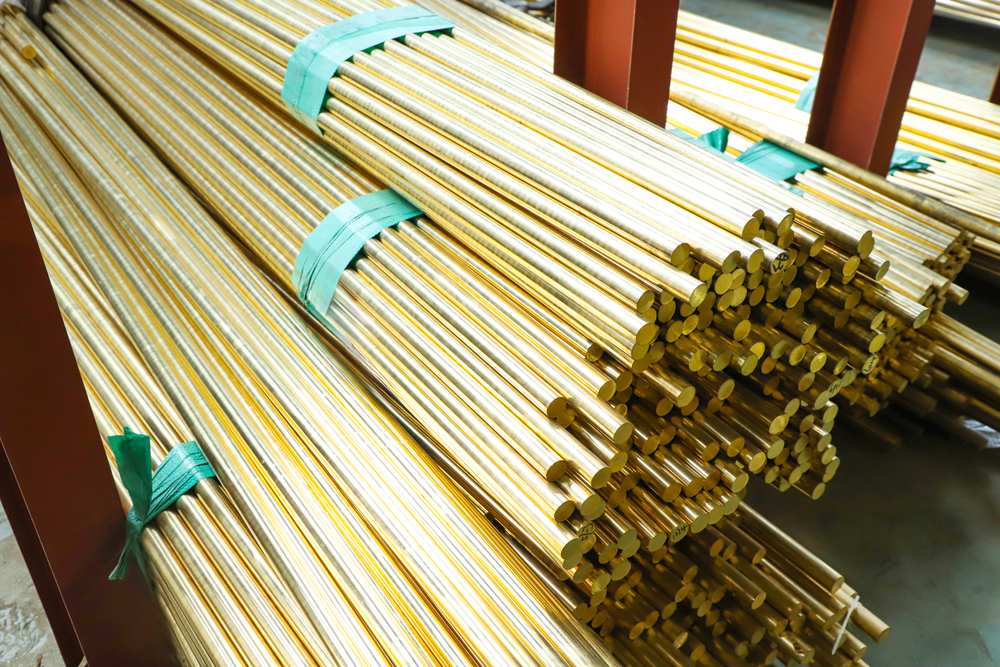
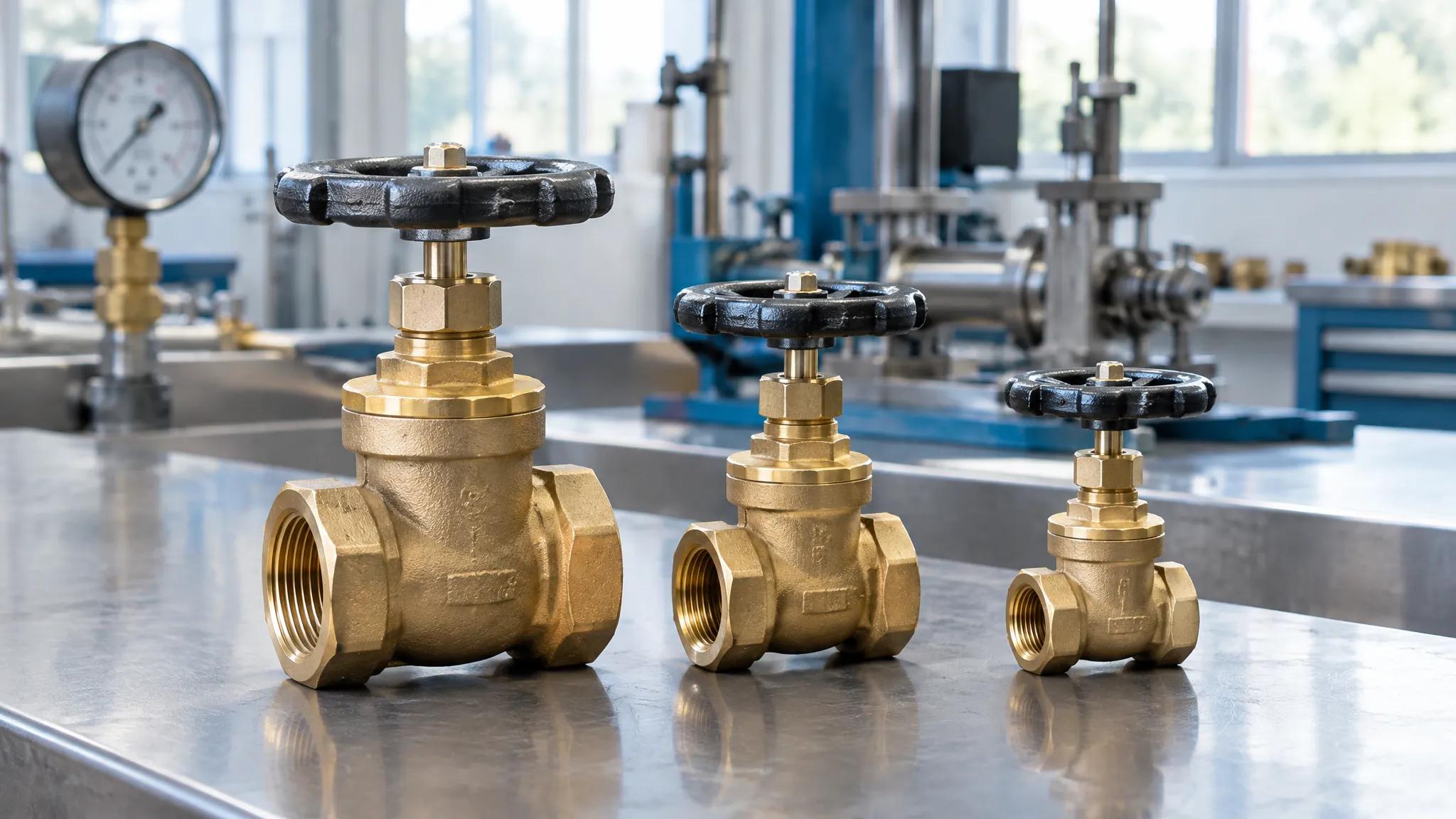
El latón lleva la rosca en la mayoría de las transiciones de plástico a metal. La aleación se elige por su maquinabilidad y comportamiento ante la corrosión, pero el estándar de rosca al que se cortó es lo que decide si la unión sella.
Una consecuencia práctica para cualquiera que compre en diferentes regiones: las roscas NPT, comunes en el suministro de América del Norte, usan un ángulo de conicidad y una forma diferentes, y no son intercambiables con las roscas R de ISO 7-1 a pesar de encajar durante un par de vueltas. Si un proyecto mezcla componentes de origen europeo y americano — lo cual sucede constantemente en conjuntos de bombas y medidores — el estándar de rosca debe verificarse por artículo, no asumirse por proyecto.
Plástico a metal: dónde se asienta el inserto y por qué se agrieta
La unión plástico-metal es la transición más común en cualquier edificio y la que tiene más formas de salir mal, porque debe satisfacer dos conjuntos de física a la vez. El lado del polímero necesita un enchufe de fusión o un enchufe con solvente dimensionado según su propia norma. El lado metálico necesita una rosca cortada según una norma de rosca. Una pieza de transición es simplemente una parte que lleva ambas geometrías, generalmente como un inserto de latón moldeado o roscado en un cuerpo de polímero.
En esta unión residen dos mecanismos de fallo independientes, y conviene separarlos porque las soluciones son diferentes.
Mecánico: el inserto es una cuña
Cuando un inserto de latón se aprieta en exceso en un cuerpo de polímero, la tensión circunferencial en el plástico aumenta hasta que el enchufe se agrieta. La grieta a menudo es invisible el día de la instalación y se abre bajo ciclos térmicos.
No existe una cifra de par publicada para esto: varía con el polímero, el espesor de pared, la geometría del inserto y la temperatura de la pieza en el momento del apriete. Por lo tanto, la regla sensata es apretar según la cifra indicada por el fabricante para esa pieza específica y, en ausencia de ella, tratar "apretado a mano más una fracción definida de vuelta" como el límite de trabajo en lugar de apretar hasta que se sienta firme. Cualquier proveedor que no indique una cifra para su propia pieza le está diciendo algo.
Electroquímico: lo que dice realmente la norma actual
Casi todos los artículos sobre fontanería con metales diferentes repiten una regla empírica sobre una diferencia de voltaje aceptable entre metales, comúnmente citada como 0.25 V. Esa regla proviene de un documento obsoleto.MIL-STD-889D, con fecha 21 de julio de 2021, cambió el método: como dice su prefacio, las revisiones anteriores "usaban la diferencia de potencial galvánico entre pares de materiales conductores para determinar la compatibilidad", mientras que en la revisión D "la velocidad de corrosión del miembro anódico del par galvánico se utiliza para determinar la compatibilidad galvánica".
El umbral que establece es una velocidad, no un voltaje. Por encima de la velocidad máxima de corrosión de compatibilidad de 0.009 mil/año, un par galvánico se considera incompatible y se requiere protección contra la corrosión. La norma se cuida de añadir que la compatibilidad no implica ausencia de otros mecanismos de corrosión, como la corrosión por grietas o por picaduras: un par compatible puede necesitar protección por otras razones.
La parte de esa norma con mayor relevancia directa para una unión de tubería es su tratamiento del área. Requiere que se eviten geometrías donde el área catódica sea mayor que el área anódica, y da la relación ánodo-cátodo requerida como A/C = (1 / 0.009 mil/año) × CR. El significado técnico en una transición es contundente: un componente anódico pequeño unido a uno catódico grande se corroe rápidamente, porque toda la corriente del cátodo se concentra en un área pequeña. Un niple galvanizado corto roscado en un tramo largo de cobre es un ejemplo clásico de ánodo pequeño. El mismo niple en medio de un sistema galvanizado está bien.
Aquí es donde una unión dieléctrica justifica su costo. Interpone un manguito y una junta no conductores entre los dos metales, de modo que se rompe el camino eléctrico y el par no puede formarse. También se acepta con frecuencia una pieza sustancial de latón o bronce entre los dos metales, razonando que una gran masa de aleación intermedia se corroe lo suficientemente lento como para durar más que el sistema.
Cuál de estas opciones puede usar su proyecto es una cuestión de código local, no universal. Los requisitos varían según la jurisdicción, la química del agua y el rol del instalador, así que confirme la regla vigente con la autoridad competente en lugar de con un catálogo. Para el lado de la aleación de la decisión, nuestra nota sobre CW617N y latón sin plomo cubre lo que significan las designaciones.
Una simplificación práctica que vale la pena recordar: una tubería de plástico entre dos metales es en sí misma una ruptura dieléctrica. Un tramo de PP-R o PE que separa una sección de cobre de una sección galvanizada elimina por completo el camino eléctrico. Los sistemas de materiales mixtos son frecuentemente menos vulnerables al ataque galvánico que los sistemas totalmente metálicos, lo cual es lo contrario de lo que la frase "mezclar materiales" sugiere a la mayoría de los compradores.
Transiciones con bridas: el círculo de pernos que parece correcto y no lo es
Por encima de aproximadamente DN50, las uniones entre materiales diferentes se realizan cada vez más con bridas. Las bridas son atractivas porque son independientes del material: un extremo de HDPE con anillo de respaldo se atornilla a una brida de bomba de hierro fundido sin ninguna química involucrada, y son reparables, algo que las uniones roscadas o fusionadas no son. La trampa es que el número PN estampado en una brida es una clase de presión, y los compradores lo leen como un patrón de pernos.
En EN 1092-1, PN10 y PN16 comparten patrones de pernos en los tamaños más pequeños y luego se separan. La divergencia no se anuncia; las bridas siguen pareciéndose entre sí.
| Tamaño | Círculo de pernos PN10 / pernos | Círculo de pernos PN16 / pernos | ¿Intercambiables? |
|---|---|---|---|
| DN150 | 240 mm / 8 × M20 | 240 mm / 8 × M20 | Sí: los patrones coinciden |
| DN200 | 295 mm / 8 × M20 | 295 mm / 12 × M20 | No: mismo círculo, diferente número de agujeros |
| DN250 | 350 mm / 12 × M20 | 355 mm / 12 × M24 | No: el círculo y el tamaño de los pernos difieren |
DN200 es la fila que cuesta dinero. Ambas clases usan un círculo de pernos de 295 mm, por lo que una cinta métrica a través de la cara de la brida da una lectura idéntica, y las dos piezas se ven intercambiables en un palé. Solo difiere el número de agujeros: ocho contra doce. Un equipo que descubre esto en la bomba tiene una instalación detenida, porque no hay solución en campo: no se pueden perforar cuatro agujeros adicionales en una brida clasificada y mantener la clasificación.
DN250 falla de manera diferente y más sutil. Los círculos de pernos difieren en 5 mm, lo suficientemente pequeño como para que los primeros dos pernos entren y lo suficientemente grande como para que los diez restantes no. El tamaño del perno también cambia, de M20 a M24, por lo que incluso los pernos en la caja son incorrectos.
La disciplina de pedido que evita todo esto es especificar la norma, la clase y el tamaño nominal juntos en cada artículo con brida, y declararlos nuevamente para la junta y el juego de pernos, que son partidas separadas y se piden rutinariamente a la clase incorrecta. Cuando un proyecto mezcla normas de bridas (una válvula perforada según ISO contra una bomba perforada según ANSI es común en plantas importadas), la transición necesita una brida adaptadora hecha a propósito, no optimismo. Nuestra comparación de conexiones de válvula con brida versus roscadas establece dónde pertenece cada tipo de extremo.
Movimiento térmico: la carga que nadie pone en el dibujo
Las transiciones que fallan meses después de la puesta en marcha, en lugar de el día de la prueba, generalmente fallan debido al movimiento. Los plásticos se expanden considerablemente más que los metales, diferentes plásticos se expanden en diferentes cantidades, y el punto donde dos de ellos se encuentran es donde la diferencia tiene que ir a algún lugar.
La documentación técnica del fabricante da los coeficientes de expansión térmica lineal para los plásticos que es más probable encontrar en el mismo edificio:
| Material | α (mm/m·K) | Movimiento por 10 m a ΔT 40 K |
|---|---|---|
| PE | 0.20 | 80 mm |
| PE-RT | 0.19 | 76 mm |
| PP-R (monocapa) | 0.15 | 60 mm |
| PE-X | 0.15 | 60 mm |
| PB | 0.13 | 52 mm |
| PP-R, reforzado con fibra de vidrio | 0.035 | 14 mm |
Un ejemplo práctico que puedes recalcular con tus propios números
Esta es una aritmética ilustrativa a partir de los coeficientes anteriores, no una medición de un proyecto específico. Tome una rama de agua caliente de 10 m en PP-R monocapa, instalada en un día a 20 °C, funcionando a 60 °C. Eso es ΔT = 40 K. Usando ΔL = α × L × ΔT, el tramo quiere crecer 0.15 × 10 × 40 = 60 mm.
Ahora suponga que los últimos 10 m de ese circuito se completaron con PP-R reforzado con fibra de vidrio, porque eso es lo que había en el camión. La sección reforzada quiere 0.035 × 10 × 40 = 14 mm. Las dos mitades están pidiendo movimientos que difieren en 46 mm, y el accesorio donde se encuentran es lo que rechaza la diferencia.
Nada en esa unión es defectuoso. Ambos materiales son conformes, ambos accesorios son correctos, y la junta termina soportando una carga que no aparece en ningún dibujo. Sustituir una tubería reforzada por una monocapa, o aceptar un envío parcial donde la mitad de los tamaños vinieron reforzados y la otra mitad no, es un cambio de especificación, no un intercambio equivalente, y es una de las formas más comunes en que un sistema de materiales mixtos adquiere una falla que nadie puede rastrear hasta una decisión.
Las respuestas de diseño son ordinarias: colocar un lazo de expansión o un brazo del desplazamiento entre el anclaje y la transición para que el movimiento tenga a dónde ir, anclar deliberadamente en lugar de dejar que un accesorio se convierta en anclaje por accidente, y mantener la transición fuera del medio de un tramo recto largo.
Lo que importa comercialmente está aguas arriba de todo eso. Si está consolidando un pedido de varios proveedores, el estado de refuerzo de cada artículo de tubería pertenece a la orden de compra, porque a 0.035 contra 0.15 estos no son el mismo producto. El Guía de reducción de presión y temperaturacubre la otra mitad de esa especificación, y la comparación entre HDPE, PVC y PP-R cubre dónde pertenece cada material en primer lugar.
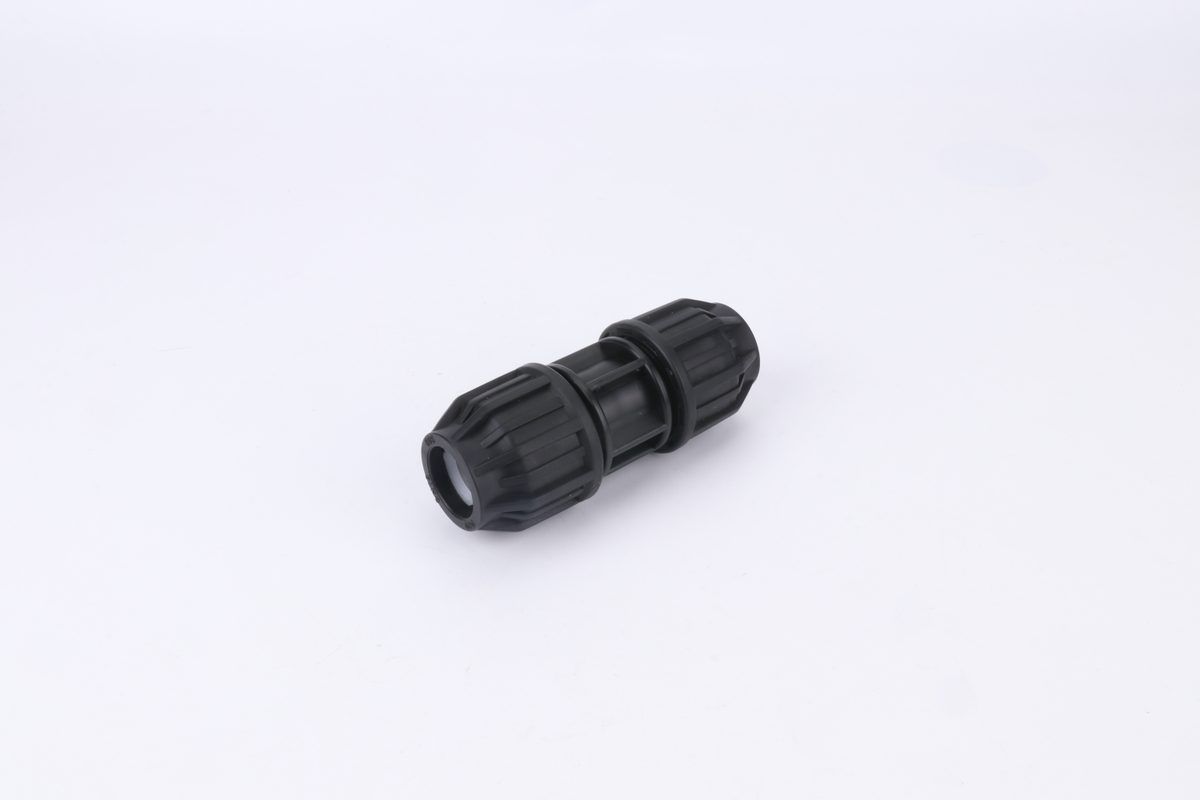
Un acoplamiento de compresión mecánico agarra la tubería en lugar de fusionarse con ella, por lo que esta familia de accesorios puede unir materiales que nunca se unirán entre sí.
Cómo pedir un accesorio de transición para que llegue la pieza correcta
Todo lo anterior converge en una orden de compra. Un accesorio de transición pedido como "adaptador macho de latón PPR ×, 25 mm × 3/4″" está subespecificado de una manera que no lo está un accesorio del mismo material, porque esa descripción omite el campo que decide si sella. Seis campos hacen que una línea de transición sea inequívoca.
- Lado del polímero, dimensionado según su propia norma: el material y el diámetro exterior según lo establece la norma de tubería — para PP-R, un DN en el rango DN20–DN160 con su clase de presión.
- Lado metálico, con la norma de rosca nombrada: no "3/4 pulgada" sino la designación — R, Rc, Rp según ISO 7-1, o G según ISO 228-1, o NPT. Este es el campo que casi siempre falta.
- Género y orientación: macho o hembra en cada lado, y para artículos con brida, la clase y la norma de perforación.
- Aleación del inserto y marcado: qué aleación es la parte metálica, y si la designación está marcada en la pieza o se suministra en el certificado.
- Condiciones de servicio: la temperatura y la clase de presión que realmente verá la unión, lo que hace que un proveedor señale una discrepancia antes de la producción.
- Certificación requerida en el destino: la marca del mercado, nombrada — este es un campo para el despacho de mercancías, no un detalle.
Lo que un catálogo dirá y no dirá — incluido el nuestro
Vale la pena decirlo claramente, porque cambia lo que debe hacer a continuación: la mayoría de los catálogos de fontanería, incluido el catálogo de productos de IFAN, enumeran los componentes de transición por familia y tamaño — adaptadores, enchufes hembra y uniones, acoplamientos roscados macho y hembra — sin imprimir la designación de rosca contra cada pieza. Esa es una práctica industrial normal y también es la razón por la que un contenedor de accesorios técnicamente correctos puede llegar cortado con la norma equivocada para el mercado al que se dirige. El catálogo le dice que la pieza existe en el tamaño que necesita. No le dice a cuál de las dos familias de roscas ISO fue cortada.
Por lo tanto, la norma de rosca debe confirmarse por escrito, por pedido, antes de la producción — en la factura proforma o en la confirmación del pedido, no en una conversación. Para un importador, esto es un correo electrónico de cinco minutos que previene una categoría de pérdida que ninguna inspección en el destino puede deshacer, porque un accesorio cortado con la norma de rosca equivocada no es defectuoso y no será aceptado como tal.
Lo que IFAN puede declarar por adelantado
Para el lado de PP-R de una transición, nuestra gama publicada es DN20–DN160 en PN12.5–PN25, producida con PP-R 100% virgen (grado PP-R 100) con certificados de lote emitidos por envío, según DIN 8077/8078 e ISO 15874. Se mantienen CE y SGS, y los certificados regionales — SASO, SONCAP, NOM — están disponibles a petición.
- Pedido mínimo: un contenedor, con tamaños mixtos aceptados dentro de él. Eso importa específicamente para las piezas de transición — se piden en docenas de variantes en pequeñas cantidades cada una, por lo que un proveedor que impone mínimos por SKU no puede servir esta parte de una lista de materiales en absoluto.
- Muestras antes del pedido: para accesorios de transición, esta es la verificación económica. Una muestra roscada en su extremo resuelve la cuestión de la norma antes de comprometer un contenedor.
- Plazo de entrega: no es una cifra que publiquemos, porque varía con la mezcla de tamaños y la temporada. Pídalo contra su lista real en lugar de en abstracto.
- Precio: cotizado por lista, no por pieza, ya que los artículos de transición son una pequeña parte de un contenedor mixto y su costo unitario depende de qué más hay en él.
Conclusión
Mezclar materiales de tubería en un mismo sistema es un problema de ingeniería resuelto con un problema de adquisición sin resolver. Las normas son claras sobre qué familias de uniones cruzan materiales y cuáles nunca lo hacen, las designaciones de rosca están publicadas y las tablas de bridas son públicas. Lo que falla es que nada de esa información viaja con la pieza: una línea de catálogo, una factura proforma y una lista de empaque pueden ser todas correctas y aun así dejar el campo decisivo sin declarar.
Si está especificando un sistema mixto, lo más valioso que puede hacer es escribir la norma de rosca y la clase de brida en sus documentos de pedido y pedir a su proveedor que las confirme. Si desea una segunda opinión sobre una unión específica, envíe los dos lados y las condiciones de servicio y pregunte qué suministrarían.
Preguntas frecuentes
¿Se pueden mezclar tuberías de PPR y PVC en el mismo sistema?
Sí, unidas mecánicamente o mediante accesorios de transición roscados. No se pueden soldar con solvente ni fusionar entre sí: el cemento para PVC no adhiere el polipropileno, por lo que cada unión PPR a PVC debe ser una pieza roscada o mecánica.
¿Cuál es la diferencia entre las roscas R y G?
R es una rosca cónica según ISO 7-1 que sella sobre la propia rosca. G es una rosca paralela según ISO 228-1 que sella sobre una cara, contra una arandela o junta tórica. Se enroscan entre sí pero no mantienen la presión de manera fiable.
¿Necesito una unión dieléctrica entre tubería de plástico y metal?
No: la corrosión galvánica requiere dos metales en contacto eléctrico, y el plástico rompe ese camino por sí mismo. Los accesorios dieléctricos pertenecen a uniones metal-metal, como acero galvanizado con cobre.
¿Puede una brida PN10 atornillarse a una brida PN16?
En DN150 y menores según EN 1092-1, sí: los patrones coinciden. En DN200 ambos comparten un círculo de pernos de 295 mm, pero PN10 tiene 8 agujeros frente a los 12 de PN16, y en DN250 los círculos y tamaños de perno difieren por completo.
¿Por qué las uniones de transición tienen fugas meses después de la instalación?
Generalmente por movimiento térmico o una norma de rosca no coincidente, más que por una pieza defectuosa. Los plásticos se expanden mucho más que los metales, y una transición en una línea larga a menudo se convierte en un punto de anclaje no intencionado.
¿Sigue siendo válida la regla de 0.25 V para metales disímiles?
Proviene de una revisión obsoleta. La MIL-STD-889D, emitida en julio de 2021, juzga la compatibilidad por la tasa de corrosión del miembro anódico, con 0.009 mil/año como umbral por encima del cual se requiere protección.