
Back or Bottom Mount Gauge: Check the Installation Envelope
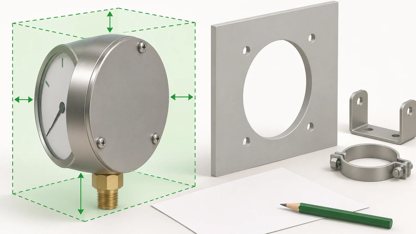
Compare a replacement gauge’s entry position, panel accessory, cutout and clearance with its exact drawing before approving the mechanical fit.
A replacement gauge can match the retained thread and still leave its dial unreadable or its case trapped against the enclosure. Choose a back or bottom connection by the installed gauge geometry, not the thread alone. Match the exact instrument drawing to the retained port, the direction from which the dial will be read, the mounting hardware and the available space. A gauge can screw into a compatible port while its case hits the enclosure or its dial faces away from the operator. Resolve those differences before approving the mechanical replacement.
The useful purchase record shows the proposed gauge in its installed position. A catalogue photograph is helpful for recognising a family, but it does not identify the ordered connection location or mounting accessory. Ask for the drawing belonging to the complete proposed configuration. Keep the thread-and-seal decision separate: the replacement gauge connection guide addresses that interface; this article addresses the space and mounting decision that remains.
Key Takeaways
- Bottom, lower-back and centre-back describe different entry geometry.
- A back connection does not automatically mean a panel-mounted instrument.
- Use the drawing for the exact model, nominal size, connection and accessory.
- Measure from identified reference surfaces rather than adding unrelated dimensions.
- Keep any prescribed relief clearance and maintenance access available.
- A mechanical fit does not establish pressure, material or measurement suitability.
Watch the background explainer
Locate the process entry before choosing the mounting hardware
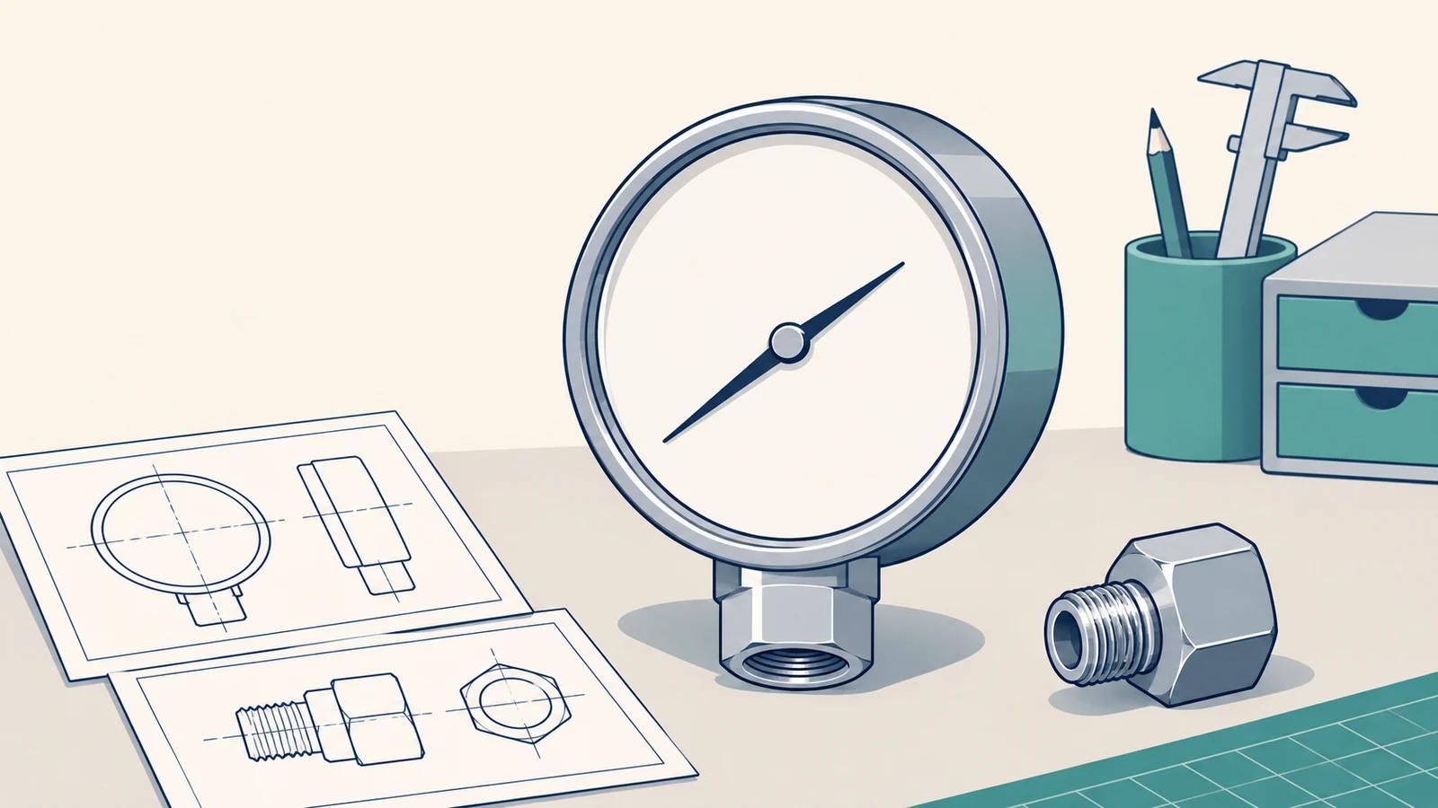
Start with a sketch of the retained installation. Mark the process port, its axis, the enclosure and the intended dial viewing direction. The distinction between a connection below the case and one behind it becomes much clearer when those references are visible. A rear connection can place the dial parallel to a panel, while a lower connection often appears on a gauge above a pipe. Those familiar arrangements are clues for identifying what to check, not proof that every model can be installed that way.
Do not collapse every rear-entry design into “back mount.” The March 2025 WIKA PM 02.02 data sheet for models 232.50 and 233.50 distinguishes lower radial, lower-back and centre-back connections. Its centre-back option is limited to nominal size NS 63. An order for a different size cannot inherit the NS 63 drawing merely because the product photographs look similar.
Connection location and structural mounting are separate selections. A flange, bracket or profile ring secures the instrument in an arrangement; it does not change a bottom connection into a rear connection. Record both selections on the purchase line. If a quotation only says “back entry, panel mounting,” ask which rear position and which accessory are included. Otherwise, the supplier and panel fabricator can agree on the words while preparing different assemblies.
Consider how the dial will be read after the enclosure door is closed and adjacent equipment is installed. A clear view on the workbench may become a view across the scale at an awkward angle. The correct response is to review the intended arrangement and the instrument instructions. Do not assume that tightening or loosening a process connection to point the dial elsewhere is an acceptable adjustment.
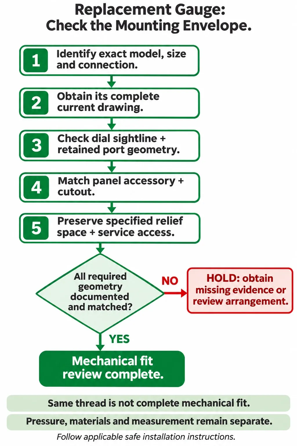
- Identify the exact model, size and connection location
- Obtain its current complete drawing
- Check dial sightline and retained port geometry
- Match the selected panel accessory and cutout
- Preserve required relief clearance and service access
- Match documented: mechanical fit only; missing input: HOLD
Read dimensions from the same drawing and reference surfaces
Take the complete model identification to the dimensional page before comparing measurements. Confirm nominal size, connection location, thread variant and any notes affecting the chosen version. Keep the drawing revision with the proposed purchase. A dimension copied from another size or accessory page can be accurate in isolation and still be the wrong input for this installation.
The centre-back NS 63 drawing on page 10 of PM 02.02 gives a concrete example. For its G ¼ B row, D1 is 63 mm and b is 33 mm. Dimension h is 57 mm; only h carries the stated ±1 mm tolerance in this row. These are different drawing dimensions, not three names for a general “gauge size.” The dimension arrows establish the surfaces represented by each symbol. Do not add b and h as if they were independent lengths: the drawing already relates them to the same instrument geometry.
Transfer the proposed instrument outline onto the installation sketch using the connection reference and the drawing arrows. Then check nearby walls, fittings and the route used to insert or remove the instrument. An empty volume behind the panel does not prove that the assembly can pass through its opening. Equally, an opening that accepts the case says nothing about the space occupied by a connector or another retained component.
A photograph with a ruler is useful for explaining an obstruction, but it should not silently replace a specified dimension or tolerance. If the panel opening is irregular, the retained port is offset or an accessory is unidentified, record that uncertainty. The outcome can be a request for a drawing or a measured site detail rather than an invented clearance allowance. Procurement can resolve that question before anyone changes the panel.
| Calculated bound | Profile ring | Panel flange |
|---|---|---|
| Lower | 64.0 | 66.7 |
| Upper | 65.0 | 67.3 |
Match the cutout to the selected flange or ring
Nominal dial size is not a panel-hole instruction. The mounting accessory can require a different opening from another accessory used with the same nominal instrument size. This matters when a replacement is being ordered for an existing panel: a familiar dial size can conceal a different retention arrangement behind the face.
Page 11 of the same WIKA data sheet lists the following NS 63 accessory examples. They belong to that documented family and accessory configuration. They are not universal cutouts for every gauge described as 63 mm.
| Selected accessory | Recommended cutout | Different geometry to retain |
|---|---|---|
| Panel mounting flange | Diameter 67 ±0.3 | Its flange and fixing-hole drawing |
| Triangular profile ring | Diameter 64.5 ±0.5 | Its retention and panel-thickness drawing |
Use the accessory drawing as a set. The cutout alone does not confirm the fixing arrangement, permitted panel thickness or access for securing the assembly. If a supplier proposes an alternative accessory, compare its complete drawing rather than keeping the previous hole specification by habit. Ask the person responsible for the panel to accept the changed arrangement before a fabrication instruction is released.
Separate a hole that is too small from a missing identification. In the former case, the documented opening and the selected drawing disagree. In the latter, the comparison cannot yet be made. Both can require a hold, but their next actions differ: revise the documented arrangement in one case and obtain the missing configuration evidence in the other. Ordering another gauge without resolving the distinction can repeat the same problem.
Keep relief space and service access in the envelope
The installation envelope includes space that must remain empty. WIKA's February 2026 pressure-gauge quick-start guide specifies a minimum 20 mm distance from each object for instruments with a blow-out device or blow-out back, so pressure can vent safely in a failure. Apply the instruction to the identified instrument and its relief arrangement. It is not a universal rear-gap rule for every manufacturer's gauge or every case construction.
Locate the actual device on the chosen version before deciding which nearby object matters. A distance measured behind one case does not establish clearance for a relief feature in another position. Do not treat a bracket, panel lining or added cover as irrelevant simply because it is outside the process connection. If it obstructs a required space, the proposed mounting needs review.
Service access is another distinct check. Show how a qualified person can reach the designated connection flats, mounting fasteners and any model-specific case arrangement without forcing the instrument against surrounding equipment. The same WIKA guide requires mounting in the depressurised state and directs connection force through the provided spanner flats rather than the case. This article provides no live-removal procedure or general tightening torque.
Retain the maker's specified operating orientation as well. Choosing a rear connection does not grant permission to turn an instrument into any position that fits the cupboard. A proposed elbow, extension or remote mounting arrangement introduces its own components and support questions. Have the responsible supplier or designer document that arrangement instead of treating it as a geometry-only workaround.
Two replacement decisions with different outcomes
Illustrative desk reviews, not site measurements or product tests: consider an existing circular panel opening recorded as 64.7 mm. The proposed NS 63 panel flange uses the page 11 recommended opening of 67 ±0.3 mm. Its stated interval is therefore 66.7–67.3 mm. The recorded opening is outside that interval. Even if the proposed thread and dial size match the old gauge, the mechanical comparison fails for this chosen flange. Hold the replacement arrangement and obtain an accepted alternative drawing or a properly reviewed panel change.
Now keep the same illustrative opening but change the documented proposal to the listed triangular profile-ring arrangement. Its recommended cutout of 64.5 ±0.5 mm gives an interval of 64.0–65.0 mm. The assumed 64.7 mm opening lies inside that interval. This resolves the cutout-size comparison for that proposed accessory; it does not establish the panel thickness, retention, connection alignment or service clearance. The record should say which comparison passed and list the remaining checks.
Suppose those remaining geometry checks are then documented against the correct drawing, the installation permits the required relief space and the intended view is clear. The reviewer can accept the mounting-envelope portion of the proposal. Range, medium, temperature, connection sealing and required verification still need their own accepted evidence. “Geometry accepted” is a useful finished result; “replacement approved for everything” would exceed what this review has established.
| Proposal | Completed comparison | Next disposition |
|---|---|---|
| Documented NS 63 panel flange | 64.7 is outside 66.7–67.3 mm | Hold this mounting arrangement |
| Documented NS 63 triangular profile ring | 64.7 is inside 64.0–65.0 mm | Cutout comparison passes; complete the other identified geometry checks |
Release an identifiable mounting record
A useful request names the retained installation and the exact proposed assembly: “Please confirm the gauge model, nominal size, entry position, connection, mounting accessory and applicable drawing revision against the attached panel and port sketch. Mark the required cutout, occupied space, relief clearance and service-access assumptions. Keep unresolved items separate from confirmed matches.” This is more actionable than a photograph accompanied by “same back-mount type.”
Preserve the final proposed drawing with the purchase line and any accepted panel change. If the supplier substitutes a model or accessory, reopen the affected comparison. A substitute with the same nominal thread can still change the case depth, connection offset or retention arrangement. Review the changed geometry without pretending that an unchanged part of the record needs to be measured again.
Read the model-specific mounting drawings for the WIKA example, or obtain the equivalent current drawing for the instrument actually proposed. Take the completed mounting record to that instrument supplier or the responsible qualified designer. This is an educational decision guide; it does not offer an IFAN gauge, mounting accessory, calibration service or approved instrument replacement package.
Conclusion
Before releasing the mechanical replacement, check five items against the identifiable drawing: entry position, panel hardware, occupied space, required empty space and service access. Record the precise comparison that passes and keep remaining application checks visible. An identical thread or nominal dial size is useful identification evidence, but neither completes the mounting decision.
FAQ
Does back entry mean panel mounting?
No. Identify the connection position and the mounting accessory separately, then use their complete documented arrangement.
Can I use the dial diameter as the cutout?
No. Use the recommended cutout for the selected model and accessory. Different mounting arrangements can require different openings.
Is a 20 mm rear gap required for every gauge?
No. The cited WIKA instruction applies to instruments with the specified blow-out arrangement. Follow the exact instrument's instructions and relief location.
Does a passed mounting comparison approve the replacement?
It approves only the assessed geometry. Connection sealing, operating conditions and measurement suitability remain separate checks.
By IFAN Group. Public-source technical explanation; the two panel-opening examples are illustrative, not field-test evidence.