

Storm Drainage Pipe Sizing: Rainfall to Required Bore
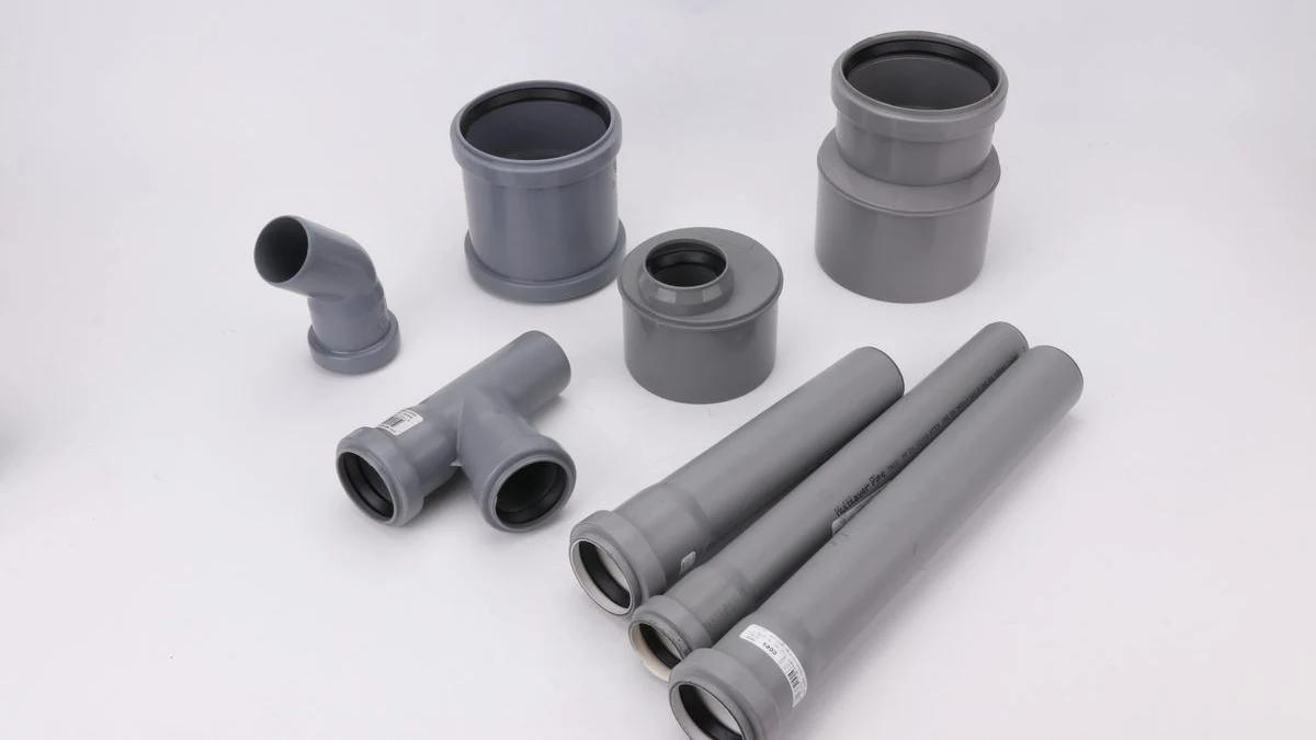
Calculate runoff from catchment and design rainfall, check pipe capacity with Manning’s equation, and separate required bore from DN, SN and final design.
A proposed storm drain has a nominal diameter and a stiffness class. Neither tells you whether it carries the design runoff. Calculate the peak flow from the catchment and approved design rainfall, then test the offered pipe’s actual internal bore with Manning’s equation. This gives a preliminary full-flow capacity screen. Inlet capture, tailwater, hydraulic grade line and local requirements still decide whether the complete drainage design works.
In the illustrative example below, a 1,000 m² catchment produces 25 L/s. A pipe with a 180 mm actual bore passes the stated full-flow check at a 1% energy slope, but fails when that slope falls to 0.5%. A 200 mm actual bore passes both screens. The result changes without changing the catchment or the pipe material.
Key Takeaways
- Design rainfall intensity needs a location, return period and appropriate duration or approved local procedure.
- With intensity in mm/h and area in m², peak runoff in L/s is C × i × A ÷ 3,600.
- Manning’s equation tests flow capacity using internal bore, roughness and energy slope.
- A nominal diameter, SN class or PN rating cannot replace actual hydraulic dimensions.
- Recheck the selected bore after changing slope, rainfall, roughness or contributing area.
- A passing barrel-capacity screen is not approval of the inlet, network or outfall.
Engineering context for the wider stormwater network. The capacity calculation and its boundaries follow below.
Which rainfall and catchment can enter the calculation?
Start at the drainage point being checked. Identify all areas that contribute to it, including upstream connections. A car park discharging through the line is not the same catchment as one isolated roof. If roofs, pavement and landscaped ground contribute together, keep each area and its runoff coefficient visible rather than assigning the whole site the coefficient of its hardest surface.
The Rational Method uses a runoff coefficient C, rainfall intensity i and contributing area A to estimate peak discharge. C is dimensionless. Its selection belongs to the accepted design method and catchment conditions. A value copied from a calculator is not evidence that the site has that runoff response.
Rainfall intensity is a rate for a defined duration and probability. Annual rainfall depth and a daily weather forecast are not substitutes. For a conventional Rational Method calculation, obtain the design intensity associated with the catchment’s time of concentration and the required return period, following the jurisdiction’s accepted procedure. The hydraulically most remote point is determined by travel time, not necessarily by the longest measured distance.
Main Roads Western Australia’s technical guidance describes time of concentration as overland, gutter and pipe travel times combined. It also requires attention to partial-area effects: a shorter, more intense storm over part of the catchment can sometimes control. That is why this guide does not prescribe one universal five-minute intensity for every site or country.
If the scheme includes detention, significant storage or a more complex catchment response, the peak-only calculation may be the wrong design tool. Main Roads explicitly distinguishes peak-flow estimation from storage design. Establish the approved hydrologic method before treating any pipe-size result as relevant.
Turn the catchment into a design flow
Keep the unit conversion visible. One millimetre of rain over one square metre is one litre of water. Multiply by the contributing area and coefficient, then convert the hourly rate to seconds:
Q (L/s) = C × i (mm/h) × A (m²) ÷ 3,600
For a mixed catchment using the same design intensity, replace C × A with the sum of each area’s C × A. Do not multiply an area-weighted coefficient by just one of the component areas.
| Input | Teaching value | What a real calculation needs |
|---|---|---|
| Contributing area A | 1,000 m² | Surveyed drainage boundary and upstream contributions |
| Runoff coefficient C | 0.90 | Approved coefficient for the actual surfaces and design method |
| Rainfall intensity i | 100 mm/h | Local design intensity with duration and return period |
| Manning roughness n | 0.011 | Accepted design value for the exact pipe and service condition |
| Energy slope S | 0.010 m/m | Hydraulic basis; pipe grade alone is not always equivalent |
All values in this example are explicit teaching assumptions. They are not a project design, rainfall recommendation, IFAN product data or local approval criterion.
Substitution gives 0.90 × 100 × 1,000 ÷ 3,600 = 25 L/s, or 0.025 m³/s. That is the peak flow to carry into the capacity check. It is not a storm volume. Multiplying this peak by an arbitrary storm duration would assume the peak continued for that whole period; the Rational Method result alone does not establish that hydrograph.
For an actual design, save the rainfall source and its selected duration and probability beside the arithmetic. If those inputs are absent, a numerical bore can still be calculated from hypothetical values, but it cannot be presented as the required site size. Once the approved intensity is available, replace the teaching value and recompute Q.
Turn design flow into an internal-bore requirement
The FHWA Urban Drainage Design Manual, HEC-22 fourth edition (2024), Chapter 9, describes Manning’s equation for storm-drain conduit capacity. In SI units, the general form for the full circular pipe used here is:
Q = (1/n) × (πD²/4) × (D/4)2/3 × √S
Q is m³/s, D is the internal flow diameter in metres, n is Manning’s roughness coefficient and S is energy slope in m/m. The area is πD²/4; the full-circle hydraulic radius is D/4. Hydraulic radius is area divided by wetted perimeter, not half the pipe diameter.
Combining the geometric constants gives Q ≈ (0.3117/n) × D8/3 × √S. HEC-22 gives the rounded SI coefficient as 0.312. Rearranging the full-circle expression for this preliminary check:
D = [Q × n ÷ (0.3117 × √S)]3/8
With Q = 0.025 m³/s, n = 0.011 and S = 0.010, the calculated bore is approximately 0.1697 m, or 170 mm. This is a hydraulic result, not a nominal product designation. Select an actually available candidate with a documented internal bore, then put that bore back into the capacity equation.
| Actual bore | Full-flow capacity (litres/s) | Compare with 25 L/s | Screening verdict |
|---|---|---|---|
| 180 mm | 29.3 L/s | Capacity exceeds assumed peak | Passes this single-run capacity check |
| 200 mm | 38.8 L/s | Capacity exceeds assumed peak | Passes with more capacity; other checks remain |
Calculated from the full-circle Manning expression above using n = 0.011 and S = 0.010. Bores are illustrative candidates, not confirmed IFAN sizes. Results are rounded to 0.1 L/s.
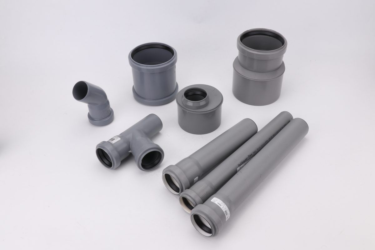
The larger bore provides more full-flow capacity under these assumptions. That does not prove it is the better whole-system design: the specified partial-flow behaviour, sediment transport, available fall, connection levels, minimum dimensions and maintenance access still matter. The uPVC drainage overview covers the wider system and specification context.
The same bore can fail at a flatter slope
Now change one input. Keep the catchment, rainfall, n and actual bores unchanged, but reduce the energy slope from 0.010 to 0.005. This is a second illustrative scenario, not a recommendation to lay a storm drain at that grade.
At a fixed diameter and roughness, Manning capacity varies with √S. Halving the slope therefore multiplies capacity by √0.5, approximately 0.707. It does not halve the capacity, and it does not leave capacity unchanged.
| Actual bore | Full-flow capacity (litres/s) | Compare with 25 L/s | Screening verdict |
|---|---|---|---|
| 180 mm | 20.7 L/s | Below assumed peak | Fails this capacity screen |
| 200 mm | 27.4 L/s | Above assumed peak | Passes this screen; final design unresolved |
Same teaching inputs and equation, with S changed to 0.005. The new calculated minimum bore is approximately 193 mm.
The 180 mm candidate passed at the first slope and fails at the second. Calling it “SN8,” changing the nominal label or citing a pressure rating does not alter its actual flow area. If its wall becomes thicker while OD stays fixed, its internal bore becomes smaller and must be rechecked. An SN class addresses stiffness; a PN designation concerns pressure, not this gravity-flow capacity.
Other changes have equally direct consequences. At a fixed bore and slope, a higher n reduces calculated capacity. Under the same Rational Method assumptions, a higher design intensity increases Q in proportion. When comparing supplier dimensions, preserve the chosen calculation basis rather than pairing a favourable bore from one product with a favourable roughness from another.
| Condition | Flow (L/s) |
|---|---|
| 180 mm / 1% | 29.3 |
| 200 mm / 1% | 38.8 |
| 180 mm / 0.5% | 20.7 |
| 200 mm / 0.5% | 27.4 |
| Assumed peak | 25 |
What the pipe calculation cannot approve
First, the inlet must capture the water. A large downstream pipe cannot recover runoff that bypasses the grate or catch basin. Inlet blockage, approach flow and surface flooding need their own design checks. A pipe-only table is incomplete where inlet capture controls the result.
Second, the outfall and network establish the hydraulic conditions. HEC-22 defines S in the capacity equation as the energy-grade-line slope. In steady uniform free-surface flow, using the conduit grade can be appropriate. A submerged outfall, backwater, junction losses or surcharged network can make that simple substitution unsuitable. Check the hydraulic grade line against the site’s relevant levels and allowable surcharge conditions.
Third, the chosen operating depth matters. Full-flow capacity is a useful screen. If the governing method requires a particular partial-flow condition, apply the appropriate depth and hydraulic geometry; do not multiply the full-flow answer by the depth fraction. Flow area and wetted perimeter change together. Conversely, a pressure-flow proposal needs a suitable hydraulic analysis and joints capable of its conditions.
Fourth, the pipe must survive and remain maintainable. Structural class, cover, installation, access, debris and sediment constraints remain separate. Local authorities can set a minimum size larger than the hydraulic result. Do not turn the illustrative slope or bore in this article into a code minimum. For a road or driveway crossing, the culvert guide addresses a different inlet/outlet-controlled application.
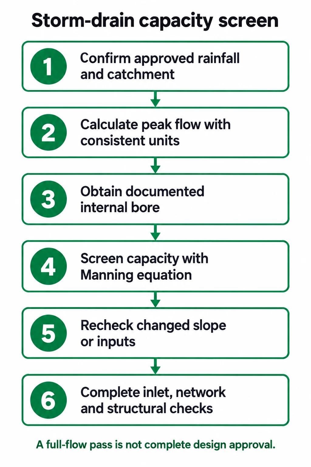
- Confirm approved rainfall and catchment
- Calculate peak flow with consistent units
- Obtain documented internal bore
- Screen capacity with Manning equation
- Recheck changed slope or inputs
- Complete inlet, network and structural checks
Carry the calculation into a pipe specification
Make the capacity result traceable before comparing products. Keep the contributing areas, coefficients, rainfall source and duration, selected Q, roughness basis, energy slope assumption and actual candidate bore together. Show both the required flow and the candidate’s calculated capacity. Then mark the checks still needed for the inlet, hydraulic grade line, local minimum size and structural installation.
A useful specification therefore distinguishes three things: the hydraulic requirement, the actual product dimensions and the product’s structural or pressure classification. “DN200, SN8” may describe two important purchasing fields, but without the applicable dimensional system and internal bore it cannot reproduce the capacity result. Ask for OD and wall dimensions or the documented flow diameter, as appropriate to the product standard.
The Review the IFAN product catalogue link is a starting point for identifying relevant pipe categories. It does not confirm that either illustrative bore is available, that a product meets a local stormwater approval, or that a complete design has been checked. Submit the project country, product standard, required dimensions, design flow and installation duty to verify a matching offering separately.
Conclusion
Before accepting a storm-drain size, check four links in the calculation: approved rainfall and catchment inputs, consistent flow units, documented internal bore and appropriate hydraulic conditions. Recalculate after a slope or specification change. Carry the capacity result into the inlet, network and structural checks; only then can the proposed product become part of a complete drainage design.
Frequently Asked Questions
Can I use daily rainfall to size a storm drain?
Not directly. Use the approved design rainfall intensity and its required duration and return period. Daily depth does not identify the relevant short-duration peak.
Is DN the diameter used in Manning’s equation?
Use the documented internal flow diameter. DN depends on the dimensional system and does not by itself establish the bore.
Does a higher SN class carry more stormwater?
SN is a stiffness classification. Hydraulic capacity depends on actual bore, roughness and hydraulic conditions; recheck the bore if the construction changes.
Does passing the full-flow check approve the pipe size?
No. Inlet capacity, tailwater, hydraulic grade line, operating depth, local minima and structural installation checks can still change the design.
Related Briefings
Storm Sewer vs Sanitary Sewer: Identify the Service Before Specifying Pipe

C900 DR 14, DR 18 and DR 25: Read a US Water Tender
Y-Strainer Selection for Water: Mesh, Pressure Drop, Blowdown
Check water Y-strainer screen openings, model pressure loss and cleanout access. Decide what fits, what is missing and when basket or duplex designs suit.