
Sélection des vannes d'isolation pour un bâtiment : quel niveau coupe quoi
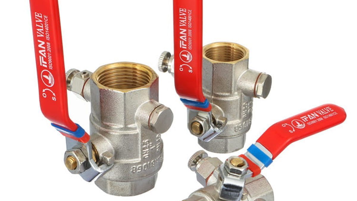
L'IPC 606.1 impose des vannes à pleine ouverture à 8 emplacements, et l'IPC 606.2 des vannes d'arrêt à 3. Un programme d'isolation à cinq niveaux, avec le rayon de coupure de chaque niveau.
Le code international de la plomberie désigne huit emplacements dans un bâtiment où une vanne à ouverture totale est requise, et seulement trois où une simple vanne d'arrêt suffit. La plupart des nomenclatures de vannes ne font jamais cette distinction. Elles listent « vanne d'isolement » contre chaque branche sur le schéma de colonne et laissent l'entrepreneur décider ce qui arrive sur le chantier — c'est ainsi qu'une vanne à restriction se retrouve à la base d'une colonne desservant neuf étages.
Cette page mappe l'isolement au bâtiment plutôt qu'au catalogue de vannes. Cinq niveaux, de l'entrée de service jusqu'au robinet d'arrêt terminal : quelle clause du code place une vanne à chaque niveau, quel type y convient, et — la question qu'un gestionnaire d'installations se pose réellement — quelle partie du bâtiment perd de l'eau lorsque vous la fermez.
- L'ouverture totale est une catégorie du code, pas une préférence. IPC 606.1 exige une vanne à ouverture totale à huit emplacements, y compris à la base de chaque colonne et à chaque entrée de logement. IPC 606.2 n'exige qu'une vanne d'arrêt à trois emplacements — tous terminaux.
- Choisissez le niveau en fonction du rayon de coupure. Une vanne à la base d'une colonne isole une colonne sur toute sa hauteur. Une vanne d'entrée de logement isole un appartement. Le niveau que vous installez détermine combien de locataires sont affectés par un changement de lave-linge.
- EN 806-5:2012 interdit la vanne à papillon. La clause 6 exige que les vannes d'arrêt soient « en position entièrement ouverte ou fermée » et soient actionnées à intervalles réguliers. Une vanne à moitié fermée est une cause documentée de débit réduit et de bruit.
- La règle des 7 jours s'applique à la réception. Une installation non exploitée dans les 7 jours suivant l'achèvement doit être fermée et vidangée, ou rincée régulièrement (EN 806-5, clause 7). La plupart des programmes d'aménagement violent cette règle sans s'en apercevoir.
- Vérifiez l'édition avant de copier une spécification. EN 13828:2025 (publiée le 28 février 2025) a remplacé EN 13828:2003, qui est retirée. Le domaine d'application actuel est DN 6 à DN 100 à PN10 ou PN16.
- EN 12288 seul ne qualifie pas une vanne à opercule pour l'eau potable. C'est une norme de vanne industrielle et elle renvoie à des normes de performance distinctes ainsi qu'à une approbation réglementaire.
Van d'isolement vs vanne d'arrêt : la distinction du code qui décide de votre nomenclature
« Vanne d'isolement » est une description de fonction, pas une catégorie de produit. Le code divise cette fonction en deux, et c'est là que commencent les erreurs de spécification.
La section 606.1 du code international de la plomberie couvre les vannes à ouverture totale — des vannes dont la position ouverte laisse le passage d'eau essentiellement sans restriction. Elle nomme huit emplacements :
- La conduite de service d'eau du bâtiment depuis l'alimentation publique, près de la bordure.
- La conduite de distribution d'eau à l'entrée de la structure.
- Le côté refoulement de chaque compteur d'eau.
- La base de chaque colonne d'eau, dans les bâtiments autres que les résidences multifamiliales de deux étages ou moins et autres que les résidences unifamiliales et bifamiliales.
- Le sommet de chaque colonne montante d'eau, dans les bâtiments autres que les habitations unifamiliales et bifamiliales.
- L'entrée de chaque conduite d'alimentation en eau d'une unité d'habitation, sauf lorsqu'elle dessert un appareil sanitaire unique muni de robinets d'arrêt individuels.
- La conduite d'alimentation en eau d'un réservoir à gravité ou sous pression.
- La conduite d'alimentation en eau de chaque chauffe-eau.
La section 606.2 couvre les robinets d'arrêt, et la liste est beaucoup plus courte. Trois emplacements : l'alimentation de chaque appareil sanitaire (autre que les baignoires et les douches dans les habitations unifamiliales et bifamiliales, et autre que les chambres individuelles déjà équipées de robinets d'arrêt dans les hôtels, motels et établissements similaires) ; la conduite d'alimentation en eau de chaque robinet de puisage extérieur ; et la conduite d'alimentation en eau de chaque appareil ou équipement mécanique.
Lisez les deux listes côte à côte et la logique apparaît
Chaque emplacement du 606.1 se trouve sur une conduite qui alimente d'autres conduites. Chaque emplacement du 606.2 se trouve en bout de course, alimentant un seul élément. C'est toute la règle. La distribution exige une ouverture totale ; la terminaison exige un robinet d'arrêt.
La raison est hydraulique, pas bureaucratique. Une vanne sur une conduite de distribution est ouverte pendant toute sa durée de vie, à part quelques heures par décennie, donc toute restriction qu'elle introduit est une taxe permanente sur chaque appareil en aval — payée chaque jour, pour toujours, sans rien acheter. Un robinet d'arrêt de puisage restreint un seul lavabo, et le brise-jet de ce lavabo le restreint bien davantage.
L'erreur se produit dans les deux sens. Spécifiez une vanne à passage intégral à chaque robinet d'arrêt et vous aurez dépensé trop pour une centaine de vannes qui ne justifieront jamais l'alésage. Spécifiez une vanne à restriction à la base d'une colonne montante et vous aurez créé une perte de charge permanente dans une colonne que vous ne pouvez pas repiper sans fermer neuf étages. Une seule de ces deux erreurs est coûteuse à corriger — et c'est celle que personne ne remarque à la réception.
Là où « isolation » et « arrêt » cessent d'être interchangeables
La terminologie varie selon les marchés. La pratique britannique et européenne tend à dire robinet d'arrêt ou vanne de service ; le code nord-américain dit pleine ouverture et arrêt ; les entrepreneurs des deux côtés disent vanne d'isolement pour tout cela. Lorsqu'une spécification franchit une frontière, cette ambiguïté voyage avec elle.
La défense consiste à écrire l'exigence, pas le surnom. Une ligne qui dit « vanne d'isolement, DN50 » peut être honorée avec n'importe quoi. Une ligne qui dit « vanne à pleine ouverture selon IPC 606.1(4), passage intégral, DN50 » ne peut être honorée que d'une seule façon. Si vous ne retenez qu'une habitude de cette page, retenez celle-ci.
Les cinq niveaux d'isolement dans un bâtiment à plusieurs étages et ce que chacun coupe
Le code vous indique où les vannes sont requises. Il ne vous dit pas ce que coûte leur fermeture en plaintes de locataires. Ce calcul est la véritable décision de conception, et il s'étend sur cinq niveaux.
Niveau 1 — Entrée de service et compteur : tout le bâtiment
L'IPC 606.1 impose des vannes à pleine ouverture à trois endroits : près de la bordure sur la conduite de service, à l'entrée de la structure et côté refoulement du compteur. La fermeture de l'une d'elles coupe l'eau de tous les appareils du site.
Ce niveau n'est utilisé peut-être que deux fois par décennie, ce qui explique précisément pourquoi il tombe en panne quand on en a besoin. Une vanne qui n'a pas bougé depuis huit ans est une vanne dont personne n'a confirmé qu'elle fonctionne encore.
Niveau 2 — Base de colonne montante et sommet de descente : une colonne verticale
C'est le niveau qui distingue un schéma de colonnes compétent d'un schéma négligé. L'IPC 606.1(4) exige une vanne à pleine ouverture à la base de chaque colonne d'eau dans les bâtiments au-delà du seuil résidentiel de deux étages ; le 606.1(5) en exige une en haut de chaque conduite de descente dans les bâtiments autres que les résidences unifamiliales et bifamiliales.
La clause sur les descentes est celle que les spécifications oublient. Dans une tour où l'eau est pompée vers un réservoir en toiture puis redescend, le sommet de la descente est le point d'isolement — et une vanne en bas de cette conduite n'isole rien d'utile, car la gravité maintient la colonne chargée au-dessus.
Certaines juridictions vont plus loin que le code modèle. Le Massachusetts (248 CMR 10.14) exige qu'« une vanne à passage intégral soit installée à la base de chaque colonne montante d'alimentation en eau lorsqu'elle dessert plusieurs appareils aux niveaux supérieurs au premier étage », et ajoute une exigence que l'IPC modèle ne précise pas : « une vanne de soutirage doit être installée en amont de chaque vanne de colonne ». La même section exige que les vannes de branche desservant plusieurs appareils soient à passage intégral, et que dans les bâtiments à plusieurs étages, une vanne à passage intégral soit installée en haut de chaque conduite d'alimentation en amont d'un système de surpression.
Cette exigence de vidange mérite attention même là où elle n'est pas obligatoire. Une colonne que l'on peut fermer mais pas vidanger est une colonne sur laquelle on ne peut pas travailler — l'eau doit quitter la conduite avant qu'un monteur puisse l'ouvrir, et sans point de vidange, elle s'échappe par l'appareil le plus bas, généralement dans un appartement.
Niveau 3 — Branche d'étage ou de zone : un niveau
L'IPC modèle n'impose pas de vanne à chaque départ d'étage ; les amendements locaux le font souvent. Le P-810.3 de Philadelphie exige que « des vannes séparées, facilement accessibles, soient placées au pied de chaque colonne montante, sur toutes les branches vers les robinets extérieurs, sur les réservoirs d'eau chaude sanitaire et sur les alimentations des appareils ».
Même là où aucune clause ne l'impose, l'isolement au niveau de l'étage est généralement le meilleur rapport qualité-prix de tout le programme. C'est la différence entre une fuite au niveau 6 qui n'affecte que le niveau 6, et la même fuite qui affecte toute la colonne du niveau 1 au toit.
Niveau 4 — Entrée du logement : un appartement
L'IPC 606.1(6) exige une vanne à ouverture totale à l'entrée de chaque conduite d'alimentation en eau d'une unité d'habitation, avec une exception : lorsque cette conduite alimente un seul appareil équipé de robinets d'arrêt individuels. En pratique, l'exception ne s'applique presque jamais en résidentiel, car un appartement comporte une cuisine et une salle de bains.
Cette vanne a une double fonction. La clause 7 de l'EN 806-5:2012 recommande que « pour éviter tout dommage par l'eau et toute perte d'eau en cas d'absence prolongée, ... le système soit isolé au robinet d'arrêt d'alimentation dans les unités résidentielles et, dans le cas des appartements, au robinet d'arrêt de la conduite pénétrant dans l'appartement. » C'est à la fois le point d'isolement pour la maintenance et celui que l'occupant doit utiliser avant un long départ — son accessibilité n'est donc pas un détail.
Niveau 5 — Robinets d'arrêt d'appareil et d'équipement : une sortie
Régi par l'IPC 606.2, pas par le 606.1 : un robinet d'arrêt sur chaque alimentation d'appareil, chaque robinet de puisage extérieur et chaque raccordement d'appareil ou d'équipement mécanique. La construction à passage intégral n'est pas requise ici, et la spécifier gaspille de l'argent là où le nombre d'unités est le plus élevé dans le bâtiment.
| Niveau | Ce qui est coupé lorsque vous fermez | Fréquence d'utilisation typique |
|---|---|---|
| 1 — Entrée de service / compteur | Chaque appareil du site | Rare — travaux sur le réseau principal, urgence |
| 2 — Base de colonne montante / tête de colonne descendante | Une colonne verticale, pleine hauteur | Occasionnelle — réparation de colonne, modification |
| 3 — Branchement d'étage / de zone | Un niveau ou une zone | Régulière — aménagement, changement de locataire |
| 4 — Entrée d'unité d'habitation | Un appartement ou une unité | Fréquente — maintenance d'unité, absence |
| 5 — Robinets d'arrêt d'appareil / d'équipement | Une sortie ou une machine | Routinière — lave-linge, robinet, remplacement d'appareil |
Lisez la colonne du milieu de haut en bas et la règle de conception s'énonce d'elle-même : chaque niveau que vous omettez reporte son travail sur le niveau supérieur, et le niveau supérieur a toujours un rayon d'impact plus large. Omettez les vannes de branchement d'étage et un joint de robinet au niveau 6 devient un arrêt de colonne. Omettez les vannes d'entrée d'unité et cela devient un arrêt d'étage pour chaque unité de ce niveau.
Le tableau des vannes : niveau, base de code, type de vanne et exigence de passage
Voici le tableau que produisent ces cinq niveaux. Il est conçu pour être repris dans un document de spécification et adapté à votre juridiction.
| Niveau | Base de code | Exigence de passage | Type adapté |
|---|---|---|---|
| Entrée de service, sortie de compteur | IPC 606.1(1)(2)(3) | Ouverture totale | Vanne à boisseau sphérique à passage intégral ; vanne à opercule pour les gros diamètres |
| Base de colonne montante | IPC 606.1(4) ; 248 CMR 10.14 ajoute la vidange | Ouverture totale / passage intégral | Vanne à boisseau sphérique à passage intégral, idéalement avec orifice de vidange |
| Tête de colonne descendante | IPC 606.1(5) | Ouverture totale | Vanne à boisseau sphérique à passage intégral |
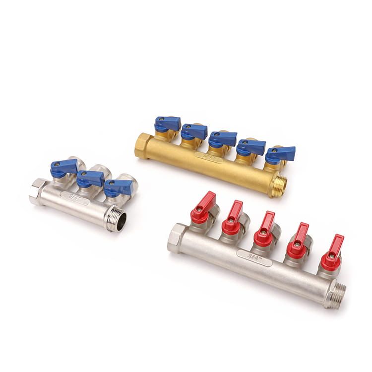
| Branchement d'étage / de zone | Amendement local (par ex. P-810.3) | Passage intégral si elle dessert plusieurs appareils | Vanne à boisseau sphérique, ou collecteur à vannes |
| Entrée d'unité d'habitation | IPC 606.1(6) | Ouverture totale | Vanne à boisseau sphérique, accessible, à levier ou à papillon |
| Chauffe-eau, réservoir de stockage | IPC 606.1(7)(8) | Ouverture totale | Vanne à boisseau sphérique adaptée au service côté chaud |
| Appareil, robinet de puisage extérieur, équipement | IPC 606.2(1)(2)(3) | Passage intégral non requis | Robinets d'arrêt d'équerre ou droit, vanne à boisseau sphérique compacte |
Quelle norme régit réellement la vanne que vous recevez
Pour les vannes à boisseau sphérique en eau potable dans les bâtiments, la référence est EN 13828 — « Robinetterie de bâtiment. Robinets à tournant sphérique en alliage de cuivre et en acier inoxydable, à commande manuelle, pour l'alimentation en eau potable dans les bâtiments. Essais et exigences. » Vérifier l'édition.La norme BS EN 13828:2025 a été publiée le 28 février 2025 et a remplacé la norme BS EN 13828:2003, désormais retirée.Un modèle de spécification rédigé il y a cinq ans cite encore l'édition retirée, tout comme une grande partie de la documentation fournisseur.
Le domaine d'application actuel couvre les DN 6 à DN 100 en PN10 ou PN16, pour une température maximale de distribution de 65 °C, avec des excursions occasionnelles jusqu'à 90 °C autorisées pour une durée maximale de 1 h. Ces deux valeurs de température sont celles à reporter dans un planning d'eau chaude — un robinet qualifié selon cette norme n'est pas qualifié pour un service continu au-dessus de 65 °C.
Les robinets-vannes sont le piège.La norme EN 12288:2010 est une norme de robinetterie industrielle — robinets-vannes en alliage de cuivre pour usage général, DN 8 à DN 500, avec des désignations de pression de PN 6 à PN 63 et des classes 150 et 300. Ce n'est pas une norme de performance pour l'eau potable en bâtiment, et elle le précise elle-même : pour des applications spécifiques telles que l'eau potable, les robinets conformes à cette norme peuvent être utilisés « à condition que les exigences des normes de performance pertinentes soient respectées », et l'approbation de l'organisme de réglementation concerné peut être requise.
Ainsi, « conforme à la norme EN 12288 » sur une soumission répond à une question que vous n'avez pas posée. Pour une application potable, vous avez également besoin de la norme de performance et, selon le marché, de l'approbation réglementaire — il convient de la confirmer auprès de l'autorité locale avant que la soumission ne soit acceptée.
Ce qu'il faut vérifier avant que le planning ne soit envoyé pour devis
Six vérifications avant que le planning ne quitte votre bureau. Chacune comble une lacune qu'un fournisseur devrait sinon deviner, et une supposition sur une soumission devient une variante sur le chantier :
- Chaque ligne indique pleine ouverture ou fermeture, en référence à la clause, et non au mot « isolation ».
- Chaque ligne côté chaud indique un régime de température par rapport au plafond continu de 65 °C et à la tolérance d'excursion de 1 h / 90 °C.
- Chaque norme porte son année d'édition — et EN 13828 se lit 2025, pas 2003.
- Les colonnes montantes en charge ont un robinet en tête, et non seulement en bas.
- Les robinets de colonne ont un point de vidange, que votre juridiction reprenne ou non la formulation du Massachusetts.
- L'adoption locale est confirmée. La logique des niveaux ici est portable ; les numéros de clause ne le sont pas. Vérifiez par rapport au code effectivement adopté dans la juridiction de votre projet — pour les projets à l'export, confirmez les exigences actuelles auprès de l'autorité locale ou d'un consultant avant de publier.
En ce qui concerne le matériau, l'alliage est une décision distincte du niveau, et elle mérite d'être prise délibérément — notre note sur lelaiton sans plomb CW617Ncouvre les exigences en matière de dézincification et de teneur en plomb. Si vous établissez le devis, le guide de référence des prix des vannes explique ce qui détermine le prix unitaire. Et le catalogue produits du site répertorie la catégorie Vannes en laiton, toutes en laiton sans plomb CW617N.
Pour les prescripteurs et les acheteurs de projets avec un échéancier de vannes en main. La commande minimale est d'un conteneur, et elle peut être mixte en tailles et en gammes de produits — donc cinq types de vannes ne signifient pas cinq fournisseurs. Le délai de réponse annoncé est de 12 heures.
Ce qui tourne mal après la livraison : vannes étranglées, stagnation et la règle des 7 jours
Un échéancier correct installé correctement se dégrade quand même, et la norme européenne d'exploitation est particulièrement précise sur ce point. EN 806-5:2012 régit l'exploitation et la maintenance des installations d'eau potable à l'intérieur des bâtiments, et plusieurs de ses clauses ressemblent à une liste des erreurs réellement commises dans les bâtiments.
Ouvertes ou fermées à fond — jamais en position intermédiaire
La clause 6 le dit clairement : « Les vannes d'arrêt et les vannes de service doivent toujours être en position complètement ouverte ou fermée et actionnées à intervalles réguliers pour garantir leur fonctionnement. »
Deux exigences se trouvent dans cette phrase. La première interdit l'étranglement : une vanne n'est pas un régulateur de débit, et l'utiliser pour ajuster une branche place l'élément de fermeture en permanence dans le flux, où il s'érode. La seconde est celle que les bâtiments négligent — actionnées à intervalles réguliers. Une vanne d'isolement qui n'est jamais manœuvrée est une vanne dont l'état est inconnu, et le moment où vous le découvrez est le moment où vous en avez besoin.
La norme traite une vanne partiellement fermée comme un défaut avec des symptômes. La clause 9.2 énumère les causes d'alimentation en eau insuffisante, et la première entrée est « vannes d'arrêt non complètement ouvertes ». La clause 9.3 énumère les causes de bruit excessif, y compris « vannes d'arrêt défectueuses ou non complètement ouvertes » et les coups de bélier « causés par des robinets de puisage à fermeture rapide ou défectueux, des vannes inadaptées, une mauvaise utilisation ou installation ou une fixation inadéquate ». Ainsi, la vanne étranglée au niveau 6 apparaît deux fois dans l'arbre de défaillance : une fois comme plainte de pression, une fois comme plainte de bruit. Les bâtiments traitent généralement ces deux symptômes séparément.
La règle des 7 jours, et pourquoi les programmes d'aménagement la violent
La clause 7 fixe un seuil que la plupart des projets ne vérifient jamais par rapport à leur propre programme : « Les installations qui ne seront pas exploitées dans les 7 jours suivant leur achèvement ou qui sont hors service pendant plus de 7 jours doivent être soit isolées par la vanne d'arrêt d'alimentation et vidangées, soit l'eau doit être rincée régulièrement. »
Réfléchissez à ce que cela signifie pour une tour résidentielle. La plomberie est testée sous pression et achevée étage par étage, puis le bâtiment attend les finitions, les ascenseurs, l'inspection et la remise des clés — couramment des mois. En vertu de cette clause, l'eau stagnante dans ces tuyaux n'est pas un état neutre : elle est soit coupée et vidangée, soit purgée selon un calendrier. La clause 9.1 nomme directement la raison, notant que là où l'eau stagne et que la température sort des limites de l'EN 806-2, « il existe un risque accru de prolifération bactérienne, p. ex. Legionella ».
La conception en étages détermine le coût de la conformité. Avec des vannes d'étage et d'entrée de logement en place, vous pouvez vidanger la section achevée et laisser le reste sous pression. Sans elles, le choix est de vidanger toute une colonne ou de purger chaque point de puisage sur celle-ci.
La même clause ajoute un seuil plus long pour le côté service : les tuyaux non mis en service immédiatement après l'achèvement ou temporairement déconnectés « doivent être fermés au niveau du branchement d'eau principal », et ceux inutilisés « pendant une période d'un an ou plus, doivent être déconnectés du branchement d'eau principal ».
Rétablir l'alimentation sans endommager le système
La réouverture est une séquence, pas une simple rotation de poignée. La clause 8 exige que les vannes d'arrêt « soient partiellement ouvertes, en commençant par la vanne d'arrêt de service », puis que les tuyaux soient « entièrement purgés en ouvrant lentement les robinets », et seulement après cela, les vannes d'arrêt sont complètement ouvertes et les tuyaux rincés. Sautez l'étape d'ouverture partielle sur une colonne montante vidangée de grande taille et vous propulsez une colonne d'air et d'eau dans les raccords à grande vitesse.
Pour une interruption courte, la norme est plus souple : ouvrir complètement les points de puisage individuels « pendant une courte période (environ 5 min) » suffit généralement à évacuer l'eau stagnante.
La vanne inaccessible est une vanne que vous ne possédez pas
La clause 11 exige que les composants nécessitant une inspection et un entretien réguliers, « et toutes les commandes (par ex. sur les vannes d'arrêt) soient facilement accessibles pour l'inspection, l'entretien et le fonctionnement », avec un accès « non obstrué par des marchandises stockées, des meubles, des revêtements, des revêtements de sol, etc. »
Chacune de ces obstructions arrive après la remise des clés, de la part de quelqu'un qui ne sait pas qu'une vanne est là. Les panneaux d'accès sont carrelés ; les colonnes montantes deviennent des espaces de stockage. Cela vaut la peine de concevoir en conséquence plutôt que de l'écrire dans un manuel d'exploitation et de maintenance que personne ne lit.
Ce que la norme ne vous donne pas
L'EN 806-5 Annexe A est normative et le Tableau A.1 fixe les fréquences d'inspection et de maintenance de routine pour 46 types de composants. Quelques exemples : tuyauterie, une fois par an. Réducteurs de pression conformes à l'EN 1567, inspection une fois par an et maintenance de routine une fois par an. Disconnecteurs à zone de pression réduite contrôlable conformes à l'EN 12729, inspection tous les 6 mois et maintenance de routine une fois par an. Clapets anti-pollution non contrôlables conformes à l'EN 13959, inspection une fois par an avec remplacement tous les 10 ans. Compteurs d'eau froide, inspection une fois par an et maintenance de routine tous les 6 ans ; compteurs d'eau chaude, tous les 5 ans.
Le Tableau A.1 ne liste pas de fréquence pour les vannes d'arrêt ou d'isolement simples.Cette absence mérite d'être signalée plutôt que masquée, car c'est là que des chiffres inventés entrent dans les spécifications. Le recours de la norme elle-même est l'article 12 : la maintenance de routine des robinets d'arrêt est effectuée conformément aux instructions du fabricant, et l'article 6 exige indépendamment qu'ils soient actionnés à intervalles réguliers. Fixez l'intervalle en fonction de la documentation du fabricant et de votre propre évaluation des risques — la norme permet également d'ajuster les fréquences en fonction de la taille et de la complexité du réseau, du type d'utilisation de l'eau, de la vulnérabilité des usagers, et du caractère permanent ou saisonnier de l'exploitation, à condition que toute dérogation soit justifiée et consignée.
Un point sur le type de robinet mérite d'être mentionné ici, énoncé comme une orientation plutôt qu'un chiffre. Comme un robinet-vanne scelle sur un coin qui traverse le chemin d'écoulement, la pratique professionnelle considère qu'il est plus vulnérable au tartre et aux débris empêchant une fermeture complète, tandis qu'un robinet à boisseau sphérique quart de tour n'a pas de tige montante susceptible de se gripper. C'est une tendance bien attestée plutôt qu'une valeur mesurée, et elle ne prime pas sur le calendrier ci-dessus.
Cela explique pourquoi les robinets quart de tour conviennent aux niveaux qui sont actionnés fréquemment. Pour la comparaison elle-même, nous la traitons directement dans robinet à boisseau sphérique en laiton vs robinet-vanne, et les variantes de robinets-vannes — NRS, OS&Y, à siège élastomère — sont couvertes dans types de robinets-vannes.
Commande selon le calendrier : un bâtiment, cinq rôles de robinets, une seule expédition
Un calendrier par niveaux crée un problème d'approvisionnement dès qu'il est terminé. Un bâtiment a désormais besoin de robinets à passage intégral dans les plus grands diamètres aux colonnes montantes, de robinets de taille moyenne aux entrées des logements, de robinets d'arrêt compacts à des dizaines de points d'usage, et probablement de collecteurs avec robinets aux branches de zone. Différentes tailles, différentes poignées, différentes quantités — et traditionnellement différents fournisseurs, chacun avec son minimum de commande.

Que mettre dans le premier e-mail
Envoyez le calendrier lui-même plutôt qu'une liste de tailles. Un fabricant qui établit un devis à partir des niveaux peut proposer un composant là où vous en aviez spécifié deux, et peut signaler les cas où une fonction sort du cadre d'une norme. Pour chaque niveau, indiquez les six éléments qui déterminent réellement le devis :
- Plage de tailles et quantité par niveau — pas un nombre total de robinets.
- Pleine ouverture ou fermeture, avec la référence à la clause.
- Classe de pression et température de service, séparément pour l'eau chaude et l'eau froide.
- Type de raccordement par niveau — fileté, à compression, ou une transition vers le système de tuyauterie utilisé.
- Norme et édition, plus toute approbation de marché requise par votre juridiction.
- Type de poignée et marquage lorsque l'accès de maintenance ou l'indication de position est important.
Minimums, vérification et ce qu'il faut régler avant l'expédition du conteneur
Chez IFAN, la commande minimale est d'un conteneur, et elle peut être mixée entre tailles et gammes de produits, avec tubes, raccords, vannes et accessoires dans le même chargement. Pour un planning à cinq niveaux, cette structure importe plus qu'un prix unitaire : c'est elle qui permet à une seule commande de couvrir tout le bâtiment plutôt que cinq minimums séparés. Les prix sont cités par référence (SKU) selon le planning, plutôt que publiés sous forme de liste, et le délai annoncé pour un devis d'usine est de 12 heures.
Réglez la voie de vérification dans la même conversation, car c'est l'étape qui détecte une non-conformité tant qu'elle est encore peu coûteuse. Demandez quelle vérification physique est disponible pour chaque niveau avant de vous engager, et mettez par écrit ce que vous prévoyez de contrôler — l'ajustement du filetage par rapport au système de tuyauterie réellement spécifié, le marquage du corps, et le dégagement de la poignée dans la colonne technique réelle. Le délai de livraison est fixé par projet en fonction du mix de tailles, plutôt que publié comme un chiffre fixe, donc demandez-le pour vos propres quantités plutôt qu'en théorie.
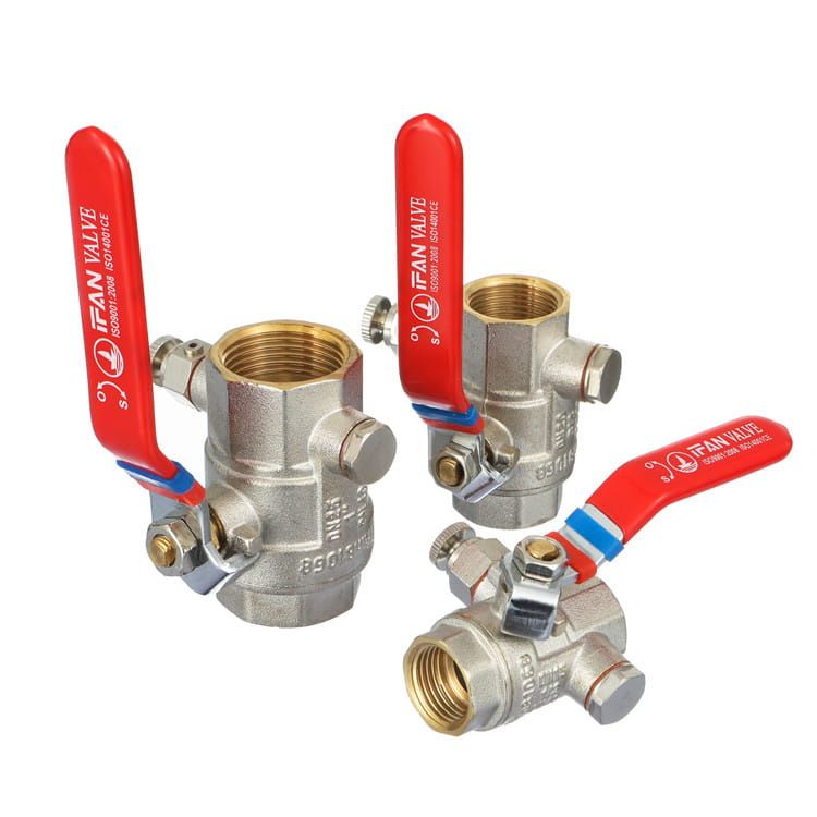
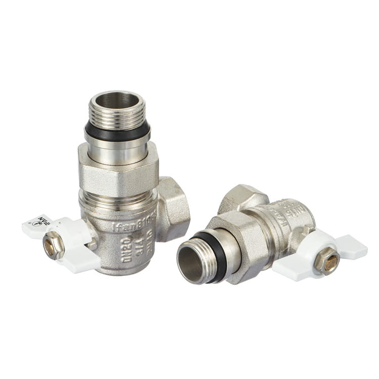
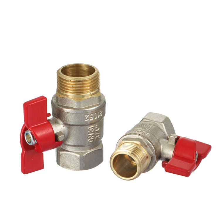
Deux étapes de vérification valent la peine d'être effectuées avant qu'un conteneur ne parte. Vérifiez le marquage du corps par rapport à ce que le planning demandait — la taille et la classe de pression moulées dans le corps, comme dans les vannes illustrées ci-dessus, plutôt qu'une étiquette imprimée qui ne survit pas à un lavage. Et confirmez l'édition de la norme sur la documentation, car un certificat citant EN 13828:2003 cite un document retiré.
L'entreprise derrière ces conseils de planning fabrique le matériel : IFAN exploite son usine depuis 1993, dispose d'une installation de 120 000 m² dans le Zhejiang avec un atelier de moulage par injection et de moules en interne, et exporte vers plus de 120 pays. Le travail de configuration des vannes — y compris les configurations de vannes sur mesure en laiton sans plomb — passe par le côté fabrication et OEM de l'entreprise.
Comment le corps est formé, et pourquoi cela détermine si le marquage signifie quelque chose
Tout ce qui précède suppose que la vanne arrivant sur site correspond à son marquage. La méthode de formage est ce qui le détermine. Les corps de vannes en laiton sont forgés à froid puis usinés avec précision : le forgeage compacte la structure du grain et laisse un corps dense, et l'usinage qui suit définit la géométrie du siège à laquelle l'élément de fermeture doit correspondre. Un marquage DN ou PN moulé n'est fiable que si la cohérence de ce processus l'est — c'est pourquoi un marquage du corps moulé dans du laiton forgé a plus de poids qu'une étiquette imprimée, et pourquoi il vaut la peine de voir la séquence de production avant de valider un niveau qui ne sera jamais re-tuyauté.
 ▶ Lecture
Processus complet en interne : forgeage à froid → usinage de précision → moulage par injection. Source : chaîne officielle du groupe IFAN.
Où cette page passe le relais
Cet article s'arrête délibérément au niveau. Les décisions un niveau en dessous ont leurs propres pages : tailles de vannes à bille en laiton pour la sélection du DN à l'intérieur d'un niveau, connexions à brides vs filetées pour savoir comment la vanne rencontre le tuyau aux plus grands diamètres, et types de vannes pour l'ensemble plus large incluant les dispositifs de pression et anti-refoulement qui partagent une salle technique avec ceux-ci.
Deux de ces dispositifs interagissent avec votre conception d'isolement et méritent d'être lus en parallèle : un réducteur de pression nécessite un isolement de chaque côté pour être maintenable à la fréquence annuelle fixée par le tableau A.1, et un clapet anti-refoulement impose une inspection semestrielle qu'une installation enterrée rend impossible à respecter.
Vos trois prochaines étapes
- Annotez le schéma de colonne par niveau, puis inscrivez le rayon d'intervention à côté de chaque vanne. Tout niveau dont le rayon est plus large que le travail qu'il desservira indique une vanne manquante un niveau en dessous.
- Réécrivez chaque ligne « vanne d'isolement » comme vanne tout-ouvert ou d'arrêt avec sa référence de clause, sa norme datée d'édition et son service en température.
- Confirmez l'adoption locale des clauses citées, puis envoyez le calendrier pour devis en un seul lot plutôt qu'en listes de tailles séparées.
Questions fréquentes
Quelle est la différence entre une vanne d'isolement et une vanne d'arrêt ?
Dans les termes de l'IPC, les vannes tout-ouvert (606.1) se placent à huit points de distribution tels que l'entrée de service, la base de colonne et l'entrée du logement. Les vannes d'arrêt (606.2) se placent à trois points terminaux : alimentations d'appareils, robinets de puisage et appareils électroménagers. « Vanne d'isolement » est un usage informel couvrant les deux.
Dois-je installer une vanne d'isolement à chaque étage ?
L'IPC modèle n'en exige pas à chaque départ d'étage, bien que des amendements locaux comme le P-810.3 de Philadelphie exigent des vannes à chaque pied de colonne et sur les branchements. Sans vannes au niveau des étages, toute réparation à ce niveau entraîne un arrêt complet de la colonne.
Puis-je utiliser une vanne d'isolement pour réduire le débit vers une branche ?
Non. La clause 6 de l'EN 806-5:2012 exige que les vannes d'arrêt soient en position pleinement ouverte ou pleinement fermée. Elle liste une vanne d'arrêt partiellement ouverte comme cause à la fois d'alimentation insuffisante (clause 9.2) et de bruit excessif (clause 9.3). Utilisez plutôt un dispositif de régulation.
À quelle norme spécifier un robinet à boisseau sphérique pour bâtiment ?
L'EN 13828 couvre les robinets à boisseau sphérique en alliage de cuivre et en acier inoxydable, à commande manuelle, pour l'eau potable dans les bâtiments. Spécifiez l'édition 2025, publiée le 28 février 2025 ; elle a remplacé l'EN 13828:2003, désormais retirée. Le domaine d'application est DN 6 à DN 100 à PN10 ou PN16.
L'EN 12288 suffit-elle pour une vanne à opercule pour eau potable ?
Pas à elle seule. L'EN 12288:2010 est une norme industrielle pour les vannes à opercule en alliage de cuivre, DN 8 à DN 500. Pour l'eau potable, elle stipule que les normes de performance pertinentes doivent également être respectées, et une approbation réglementaire peut être requise.
À quelle fréquence les vannes d'isolement doivent-elles être manœuvrées ?
Le tableau A.1 de l'EN 806-5 fixe des fréquences pour 46 types de composants mais n'en donne aucune pour les vannes d'arrêt simples. La clause 6 exige une actionnement à intervalles réguliers et la clause 12 renvoie aux instructions du fabricant — définissez l'intervalle à partir de celles-ci et de votre évaluation des risques.
Que se passe-t-il si un nouveau bâtiment reste inoccupé après la fin des travaux de tuyauterie ?
La clause 7 de la norme EN 806-5 exige qu'une installation non exploitée dans les 7 jours suivant son achèvement, ou hors service au-delà de 7 jours, soit isolée au niveau du robinet d'arrêt d'alimentation et vidangée, ou purgée régulièrement. La stagnation augmente le risque bactérien, notamment la légionellose.