
Gate Valve Types: NRS, OS&Y and Resilient-Seated Explained
Ask ten suppliers for a "gate valve" and you will get ten different products. The word describes a family, not a part number. Inside that family, three decisions actually change what arrives on site: whether the stem rises out of the valve or stays put (OS&Y versus NRS), whether the wedge seals metal-on-metal or against rubber (resilient-seated versus metal-seated), and what the body is cast from. Those three choices decide whether the valve can be buried, whether a fire marshal will accept it, and whether it still seals in fifteen years.

Key Takeaways
- NRS vs OS&Y is a space-and-indication trade, not a quality trade. Both appear inside the same standards — ANSI/AWWA C509 and C515 each cover non-rising stem and outside screw-and-yoke arrangements.
- Fire service wants OS&Y for a documented reason. NFPA 13 requires a listed indicating valve on each water supply source, and listed indicating control valves must not close in under 5 seconds at maximum operating speed.
- Resilient-seated beat metal-seated on two specific defects: metal-to-metal seats carry allowable leakage from the factory that worsens with time, and metal-on-metal sealing contact produces friction and high operating torque.
- Body material outranks wall thickness. Ductile iron (ASTM A536 65-45-12) has at least 65,000 psi tensile strength against grey iron's 31,000 psi, plus 12% minimum elongation — grey iron has practically no ability to flex before fracture.
- A buried hand-operated gate valve is not a duty-cycle device. EN 1074 requires manually operated isolating valves to be designed for just 250 cycles, versus 2,500 for powered ones.
- IFAN supplies the brass small-bore end only: DN15–DN50 threaded. Above roughly DN65 this becomes an iron-body waterworks purchase from an AWWA C509/C515 or EN 1171 foundry — not from us. That boundary is stated plainly below.
What Actually Varies Between Gate Valve Types
A gate valve does one job: it drives a flat or wedge-shaped closure member square across the bore to shut flow off, and retracts it fully clear to open. That geometry is why gate valves dominate isolation duty — fully open, the gate sits up inside the bonnet and the bore is effectively unobstructed, so pressure loss is close to nothing and a pig or swab can pass. It is also why gate valves are poor at throttling: a partially open gate sits in the flow stream, vibrates, and erodes its own sealing faces.
Given that shared job, the variation between "types" comes down to three independent axes. Buyers routinely collapse them into one, which is how you end up with a specification that describes a valve nobody manufactures. The authors of the June 2023 Journal AWWA review of gate valve specifications name this exact failure: specifications that "enlist contradictory features from multiple standards, requiring a valve that may not even exist."
| Axis | Options | What it decides |
|---|---|---|
| Stem arrangement | NRS / OS&Y (rising) | Headroom needed, whether position is visible, whether it can be buried |
| Seat design | Resilient (rubber-faced wedge) / metal-seated | Leak-tightness over time, operating torque, tolerance of grit |
| Body material | Brass / ductile iron / grey cast iron | Size range available, impact and beam-load survival, which standard applies |
These axes are genuinely independent. You can buy a resilient-seated NRS ductile-iron valve, a resilient-seated OS&Y ductile-iron valve, or a metal-seated NRS grey-iron valve. What you cannot sensibly buy is a buried OS&Y valve, and that single incompatibility explains most of the confusion in this category. If you are still deciding between a gate valve and another closure type entirely, our guide to valve types across the whole family covers that layer; this article assumes you have already landed on a gate valve.
NRS vs OS&Y: Where the Stem Goes
In a non-rising stem (NRS) valve, the stem threads engage the gate itself, inside the body. Turn the handwheel or the operating nut and the stem rotates in place while the gate climbs the thread. The stem never gets longer. Nothing protrudes. From outside, an open NRS valve looks identical to a closed one.
In an outside screw-and-yoke (OS&Y) valve, the threaded portion of the stem sits outside the pressure boundary, in a yoke above the bonnet. Turn the handwheel and the stem itself travels up out of the yoke as the gate opens. The exposed stem length is the position indicator: fully extended means fully open, and you can read it from across a plant room at a glance.
The point buyers miss is that this is not a tier system. It is a location decision, and the standards treat it that way. ANSI/AWWA C515 covers reduced-wall resilient-seated gate valves with both non-rising stems and outside screw-and-yoke rising stems, and ANSI/AWWA C509 does the same for the full-wall lineage. The stem arrangement is a selectable option inside one standard, not a separate standard and not a grade.
Where the two arrangements genuinely diverge is available size range. Under C515, the non-rising stem versions run from 3-inch (75 mm) up to 54-inch (1350 mm) nominal pipe size, while OS&Y rising-stem versions stop at 16-inch (400 mm). That asymmetry is not arbitrary: a rising stem on a 36-inch valve would be an enormous, vulnerable, and expensive column of exposed thread. Beyond a certain diameter the market simply does not build them.
| NRS (non-rising stem) | OS&Y (rising stem) | |
|---|---|---|
| Headroom required | None beyond the handwheel | Roughly one bore diameter of clear travel above the yoke |
| Position visible? | No — needs a separate indicator post or counting turns | Yes — stem travel is the indication |
| Can be buried | Yes, with a valve box and extension spindle | No — the exposed thread cannot be buried |
| Stem thread exposure | Inside, wetted by the medium | Outside, dry but exposed to atmosphere and damage |
| Size ceiling (AWWA C515) | Up to 54 in. (1350 mm) | Up to 16 in. (400 mm) |
| Typical home | Buried distribution mains, tight risers, meter chambers | Fire sprinkler risers, pump rooms, plant above ground |
One consequence deserves spelling out because it causes real site failures. Because the NRS stem thread lives inside the valve, it is permanently wetted by whatever flows through the pipe. In clean treated water that is a non-issue. In water carrying sand, silt or aggressive chemistry, that internal thread is the component that seizes — and by the time anyone notices, the valve is buried under a road. This is the argument for putting the money into an NRS valve's internal materials rather than into a fancier above-ground option that the installation will never use.
Why Fire Protection Insists on OS&Y
The fire service preference for OS&Y is not tradition. It is written into the installation standard, and it has two distinct mechanical requirements behind it that are worth separating, because contractors regularly satisfy one and fail the other.
The first is indication. NFPA 13, the standard for the installation of sprinkler systems, requires at least one listed indicating valve on each source of water supply, in an accessible location. An OS&Y valve satisfies this inherently: its stem position is the state display. A closed sprinkler control valve is the single most common cause of a sprinkler system failing to perform, so the code's insistence on a valve whose state can be read at a glance is a direct response to that failure mode.
The second is closure speed, and this is the requirement that quietly eliminates quarter-turn alternatives. NFPA 13 states that listed indicating control valves shall not close in less than 5 seconds when operated at maximum possible speed from the fully open position. A multi-turn gate valve satisfies this by geometry — you physically cannot spin a handwheel through its full travel in under five seconds. The rule exists to prevent water hammer: slamming a large water column to a stop generates a pressure surge that can rupture pipework and fittings downstream. A lever-operated quarter-turn valve on a fire main is a water-hammer generator, which is why you do not see them in that slot.
Beyond the valve itself, how you secure it changes your inspection burden. Common practice under NFPA 25 ties inspection frequency to the securing method: control valves left unsecured need weekly inspection, valves locked or sealed in the open position move to monthly, and electronically supervised valves with a tamper switch extend to quarterly. Treat those intervals as the general practice pattern rather than a specification to procure against, and confirm against the current edition of NFPA 25 for your jurisdiction — but the direction of the trade is stable and worth costing: a tamper switch is a one-time cost that buys a permanent reduction in inspection labour.
Specification trap. "OS&Y" describes the stem arrangement only. It says nothing about whether the valve is listed for fire service. A listing (UL, FM or the local equivalent) is a separate certification against a separate test regime. An OS&Y valve without that listing will not be accepted on a sprinkler system no matter how correct its stem is — and asking a factory to supply "OS&Y, fire rated" without naming the listing body is how buyers end up with an uncertified valve that looks right.
Resilient-Seated vs Metal-Seated: the Sealing Decision
Metal-seated gate valves, cast in grey iron, have been produced since the 1800s. The Journal AWWA review is blunt about the two weaknesses inherent in that design: metal-to-metal seats have allowable leakage from the manufacturer that worsens with time, and metal-to-metal contact along the sealing surfaces produces friction and high operating torques.
Read that first point again, because it is the one that surprises buyers. A metal-seated gate valve is permitted to leak when new. It is not a defect and it is not grounds for rejection — the standard allows it. If your application needs genuine bubble-tight shutoff for isolation before working on a live main, a metal-seated valve was never going to give you that, and no amount of supplier pressure will change the physics.
The resilient-seated design addresses both weaknesses with one change: a monolithic, rubber-faced wedge that is leak-tight and yields lower operating torques. Instead of a metal wedge grinding into metal body seats, a rubber-encapsulated wedge compresses against the coated body bore. Because it deforms slightly, it accommodates minor grit and small imperfections in the seating surface rather than being scored by them.
There is a second-order consequence of the resilient design that almost nobody explains, and it changes how you should inspect an incoming shipment. In a resilient-seated gate valve, the interior coating of the body serves as the mating sealing surface — the rubber wedge seals against the epoxy, not against bare iron. Val-Matic's engineering paper on waterworks coatings states this directly and notes the coating must also resist abrasion and erosion under high localised fluid velocities. It also explains why European resilient-seated gate valve makers led the entire valve industry into epoxy coatings from the 1970s, decades before quarter-turn ball and butterfly AWWA standards adopted epoxy as standard interior coating in 2010.
The practical takeaway: a coating holiday in the seating area of a resilient-seated gate valve is not a corrosion problem, it is a sealing failure. When you inspect a delivered valve, the seating band is where a coating defect actually costs you the function you bought. Most incoming inspections check the flange faces and the exterior paint and never look at the seat band.
Body Material: Why Grey Iron Lost
The standards lineage tells this story cleanly. AWWA C500, the metal-seated gate valve standard, did not receive its current designation until 1952, but its origins as the first US gate valve standard date to 1913. Its minimum wall thicknesses were based largely on experience, application, and the grey-iron casting methods of the day — limitations that, in the authors' own assessment, made those wall thicknesses "somewhat arbitrary."
ANSI/AWWA C509 followed in 1980, bringing the resilient seat to the US market. But here is the detail that matters for anyone comparing spec sheets: C509's published wall thicknesses were simply carried over from C500, which as the authors put it makes the C509 wall thicknesses arbitrary as well. Thick walls in a C509 valve are inherited casting practice, not calculated engineering.
C515 broke that inheritance. After Waterous Company began field trials on a reduced-wall ductile-iron gate valve in 1985, the C515 standard was published in 1999 with thicknesses derived from modern engineering techniques including finite element analysis, plus product verification through validation testing. The material change is what made thinner walls defensible: ASTM A536 Grade 65-45-12 ductile iron has a tensile strength of at least 65,000 psi, more than twice grey iron's 31,000 psi (ASTM A126 Grade B), along with 45,000 psi minimum yield strength and 12% minimum elongation. Grey iron, by contrast, has practically no ability to flex before fracture.
Buyers frequently reject C515 valves on the grounds that "the wall is thinner." Two published facts undercut that reflex. First, the gap is smaller than the tables suggest, because C509's published dimensions carry an allowable 12.5% reduction for manufacturing tolerance while C515's published thicknesses are minimums with no under-tolerance. Adjusted for that, a 12-inch valve compares as follows:
| Valve size | AWWA C500 / C509 (in.) | AWWA C515 (in.) |
|---|---|---|
| 4 in. | 0.35 | 0.31 |
| 8 in. | 0.44 | 0.34 |
| 12 in. | 0.60 | 0.38 |
| 24 in. | 0.95 | 0.62 |
| 36 in. | 1.35 | 1.31 |
Minimum wall thickness adjusted for allowable minus tolerances. Source: Journal AWWA, June 2023, Table 1.
Second — and this is the evidence that should settle the argument — the reduced wall was validated destructively. AMERICAN Flow Control drilled half-inch-diameter spots a quarter-inch deep into high-stress locations identified by finite element analysis on both designs, simulating worst-case advanced corrosion, then pressurised both to failure.
| Variable | 12-in. grey iron valve | 12-in. ductile-iron valve |
|---|---|---|
| Rated working pressure | 200 psig | 250 psig |
| Undrilled wall (average) | 0.70 in. | 0.44 in. |
| Drilled wall (average) | 0.45 in. | 0.19 in. |
| Pressure at failure | 850 psig | 1,200 psig |
| Method of failure | Fracture along drilled spots | Blown bonnet gasket |
Source: Journal AWWA, June 2023, Table 2, "Pressure-Related Fracture Due to Simulated Corrosion".
The ductile-iron valve had less than half the compromised wall of the grey-iron one and still held 350 psig more. More importantly, look at the failure mode: the grey-iron valve fractured, while the ductile-iron casting never broke. A temporary flexing of the bonnet let the gasket slip out of position, and the castings experienced no permanent deformation or damage. One failure mode leaves you with a broken valve in the ground; the other leaves you with a valve that needs a gasket.
The beam-load test makes the same point for the load case a buried valve actually sees — settlement of soil, structures and pipe misalignment. Vertical load was applied until fracture. The grey-iron C509-style valve fractured at the lower valve flange at 78,000 pounds with under an inch of vertical displacement. The ductile-iron C515-style valve withstood 135,000 pounds with roughly 2 inches of displacement and never failed at all; the piping system failed instead, at the threaded-on flange. If your ground moves — reclaimed land, seasonal water table, heavy traffic loading — that is the number that should drive the material choice, not the wall table.
What EN 1074 Says About Cycles and Torque
Buyers in EN-standard markets have a different set of numbers to work with, and two of them are far more useful for procurement than anything on a typical datasheet. EN 1074-2:2000, the fitness-for-purpose standard for isolating valves in water supply, was published on 18 April 2000 and amended by A1:2004 in April 2004.
The first number is design cycle count, and it reframes what a buried gate valve actually is. Per AVK's published statement of the EN 1074 regime it certifies against, manually operated isolating valves must be designed for 250 cycles, while electrically, hydraulically and pneumatically operated valves must be designed for 2,500. That factor of ten is the standard telling you plainly: a hand-operated buried isolation valve is not a duty-cycle device. If your operating philosophy involves exercising every valve on the network quarterly for twenty years, you are planning roughly 80 cycles of a 250-cycle design life on a component whose replacement requires excavating a road. Worth noting for comparison: AVK states it designs all its valves up to DN1200 for 2,500 operations even though only 250 are required — which is exactly the kind of margin question to put to any supplier rather than assuming.
The second number is maximum operating torque (MOT), and it is the one that determines whether your crew can actually close the valve with the tools on the truck. For manually operated valves without an operating device, EN 1074 sets MOT for gate valves as 1 × DN newton-metres — so a DN200 gate valve may require up to 200 Nm to operate. (For butterfly valves the figure is a flat 125 Nm.) That is a concrete planning number: it tells you the T-key length and the operator strength or gearbox you need at each size, before anyone is standing in a chamber discovering the valve will not budge. AVK states it tests its own valves down to 0.6 × DN depending on size, which again is a specific, checkable question to ask a supplier: what is your actual measured MOT at this DN, not the standard's ceiling?
The verification pressures are worth recording too, because they are what a factory acceptance test should reference: the shell test is conducted at the higher of PEA or 1.5 × PFA, and the seat test at a differential pressure of 1.1 × PFA with water.
Coatings, Lead Content and Potable Compliance
Because the body coating is a sealing surface in a resilient-seated valve, the coating specification is a functional specification, not a finish. AWWA C550 governs it, covering valves and hydrants for water, wastewater and reclaimed water service across a pH range of 4 to 9. Epoxy coatings qualify for that service by 90-day immersion tests across the full pH range at 158°F.
Here is where a lot of project specifications are quietly over-written. Because gate valve geometry is intricate and uniform coating is costly to achieve and verify, the associated valve standards require only a minimum coating thickness of 6 mils for gate valves and 8 mils for quarter-turn valves — while project and manufacturer specifications typically call for 8 to 16 mils. Holiday testing (the voltage test that finds pinholes) is likewise an optional requirement based on the purchaser's willingness to bear the cost, not a mandatory production step. If you assumed every valve arriving on your project had been holiday-tested, it almost certainly has not, unless you specified and paid for it.
The coating type also has a schedule consequence that catches installers out. Liquid epoxy dries for handling in typically 7 to 10 hours, but water immersion may require 5 to 10 additional days of cure to assure full dispersion of the solvents. Fusion-bonded epoxy needs no such additional cure, because no solvents are used. If a valve is going into a line that will be charged and pressure-tested within days of delivery, FBE is not a preference — it is the one that fits the programme.
The substitution trap. Purchasers are warned in valve standards that specifying alternate coatings or materials will invalidate the valve's NSF 61 certification. If you ask a factory to swap the coating to hit a price or a lead time, you may have just voided the potable-water certification you are contractually required to deliver — and the factory is under no obligation to point that out.
On lead content, two different standards get conflated constantly, and the distinction decides which certificate you should be demanding. Under Section 1417 of the US Safe Drinking Water Act, "lead free" means a weighted average of 0.25% lead calculated across the wetted surfaces of pipes, pipe fittings, plumbing fittings and fixtures, and 0.2% lead for solder and flux. Note "weighted average across wetted surfaces" — it is not a per-component ceiling, which is why a compliant assembly can contain individual parts above 0.25%.
That calculation method lives in NSF/ANSI/CAN 372, which establishes a limit on the lead contained within water-contact materials. NSF/ANSI 61 is a different test entirely: it establishes limits for what migrates into the water, measured by exposing products to test water during a 14-day immersion test. A supplier who answers "yes, it's NSF" without saying which number is either not paying attention or hoping you are not. For potable brass specifically, the material grade is the root of the answer, and we cover that in detail in our breakdown of CW617N and lead-free brass.
What IFAN Actually Supplies — and Where We Stop
Everything above describes the full gate valve landscape, including the buried municipal range. We do not supply most of it, and saying so plainly is more useful to you than a vague implication that we can quote anything.
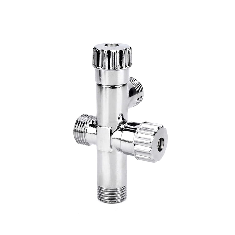
IFAN manufactures small-bore brass valves and fittings, plus thermoplastic piping systems. Our brass gate valve range is DN15–DN50 with threaded ends to BSP or NPT, in CW617N brass. That is the range covered in our dedicated brass gate valve product guide.
We do not manufacture ductile-iron or grey-cast-iron waterworks gate valves. We do not produce to AWWA C500, C509, C515 or EN 1171, and we do not supply the buried municipal valve range those standards govern — which under AWWA C515 runs from 3 in. (DN80) up to 54 in. (DN1350) in non-rising-stem form. If your project needs a flanged, resilient-seated, iron-body NRS valve for a distribution main, you need an iron foundry with those specific standard approvals — that is not us, and buying it from a brass valve manufacturer would be a mistake regardless of who was selling.
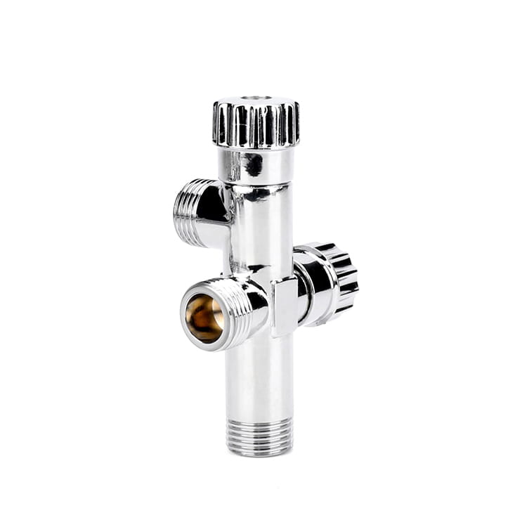
The practical handover point falls between the two. AWWA C509 and C515 both begin at 3 in. (DN80), and our brass range ends at DN50. That leaves DN65–DN80 as the band where a project stops being a brass-valve purchase and becomes an iron-body waterworks purchase. Both endpoints of that band are hard facts; where exactly you cross within it is a judgement call about your line and your pressures, not a rule.
| Requirement | IFAN brass, DN15–DN50 | Iron-body waterworks, DN80+ |
|---|---|---|
| Building risers, branch isolation, meter sets | Best fit — threaded, compact, container-friendly | Oversized and needlessly expensive |
| Buried distribution main isolation | Not for this — wrong size class and end type | Correct — flanged NRS, valve box, extension spindle |
| Sprinkler system control valve | Not supplied — we hold no fire-service listing | Correct, from a UL/FM-listed maker |
| Small-bore potable duty | Best fit — CW617N body; ask for a lead-free alloy where a lead limit applies | Applies, but not at these diameters |
| Mixed-size container for a distributor | Best fit — MOQ one container, mixed sizes accepted | Rarely available mixed at this scale |
On the manufacturing side, what we can put behind the brass range is real: the factory has run since 1993, occupies a 120,000 m² facility in Zhejiang, and operates 30+ automated extrusion lines with in-house injection moulding, its own mould workshop, and an ISO testing lab. We export to 120+ countries and accept a one-container MOQ with mixed sizes. Our declared standards — DIN 8077/8078, ISO 15874, CE, SGS, with SASO, SONCAP and NOM available on request — cover the thermoplastic piping lines; they are not AWWA or EN 1171 valve certifications and we do not present them as such. The full picture is in our certification documentation, and the current range sits in the product catalogue.
Buying small-bore brass isolation at container volume?
For distributors, contractors and project procurement teams sourcing DN15–DN50 threaded brass valves by the container, with mixed sizes on one order. If your requirement is above DN65 or needs an AWWA/EN iron body, we will tell you that instead of quoting it.
See the brass valve rangeHow to Choose: Five Questions in Order
Work these in sequence. Each answer eliminates options, and taking them out of order is what produces the contradictory specifications the AWWA authors describe.
1. Will it be buried? If yes, the stem decision is made for you: NRS, because an OS&Y stem thread cannot be buried. Add a valve box and extension spindle to the scope now, not later.
2. Does anyone need to read its position without touching it? If yes — and on a fire system the code requires it — you need OS&Y or a separate indicator post. This is the question that decides whether stem visibility is worth the headroom.
3. Does it need to seal bubble-tight? If yes, resilient-seated, without exception. Metal-seated valves are permitted allowable leakage when new, and it worsens over time. Do not litigate this with a supplier; the standard is on their side.
4. What is the diameter? Under DN50, you are in threaded brass territory. Over DN80, you are buying an iron body to AWWA or EN, and the OS&Y option itself disappears above 16 in. under C515. Between DN65 and DN80, decide deliberately rather than by habit.
5. What will the ground and the water do to it? Moving ground argues for ductile iron on beam-load performance. Gritty or aggressive water argues for scrutinising the internal stem thread on an NRS valve and the coating integrity in the seating band. Neither of these appears on a standard datasheet, so both have to be asked.
A Worked Example: One Site, Three Valves
Take a mid-rise residential block on a new development, fed from a municipal main. Three isolation points, three different correct answers — which is exactly why "gate valve types" is a question worth asking properly.
The main tapping, DN150, buried under the access road. Buried settles the stem question: NRS. The traffic loading and a development on made ground settle the material question: ductile iron to C515, on the beam-load evidence — 135,000 pounds with no fracture versus 78,000 pounds to fracture for grey iron. Resilient-seated, because this is the valve that has to genuinely shut off before anyone opens the main. Rated working pressure 250 psig at that class. Not an IFAN product; this is an iron-foundry purchase.
The sprinkler riser control valve, DN100, in the pump room. Above ground and code-driven: OS&Y, listed and indicating, per NFPA 13's requirement for a listed indicating valve on each supply source. Multi-turn by necessity — it must not close in under 5 seconds. Fit a tamper switch and the inspection interval moves from weekly to quarterly under common NFPA 25 practice, which pays for the switch quickly on a managed building. Again not an IFAN product, because we hold no fire-service listing.
The apartment branch isolations, DN20 and DN25, in service ducts. Small bore, threaded, potable, and there are hundreds of them. CW617N brass, BSP threads, non-rising stem because the duct has no headroom and nobody reads valve positions in a service riser anyway. This is the IFAN part of the job — and at that quantity, the fact that mixed sizes ship in one container matters more to the buyer than any single spec on the sheet.
One site, three valves, and the only thing they share is the word "gate." If a supplier offers to quote all three from one catalogue without asking which is buried and which is on the fire main, that tells you something useful about the supplier. For the comparison one level up — whether a gate valve is even the right closure type at each of these points — see our ball valve versus gate valve comparison.
Conclusion
Gate valve types resolve into three independent choices, not a quality ladder. NRS or OS&Y is decided by whether the valve is buried and whether anyone must read its position. Resilient or metal-seated is decided by whether you need real shutoff, and the published allowable leakage on metal seats makes that decision for most potable applications. Body material is decided by what the ground and the water will do over decades, with the ductile-iron beam-load and burst evidence pointing one way clearly.
If your requirement lands in DN15–DN50 threaded brass, that is what we make and we are glad to quote it. If it lands above DN65 in an iron body, buy it from a waterworks foundry — we would rather tell you that now than after the container ships.
Frequently Asked Questions
Is OS&Y better than NRS?
No — they solve different problems. Both are covered inside the same standards (AWWA C509 and C515 each include both arrangements). OS&Y gives visible position indication above ground; NRS needs no headroom and can be buried. A buried OS&Y valve is simply wrong, not premium.
Can a gate valve be used to throttle flow?
No. A partially open gate sits in the flow stream, vibrates and erodes its own sealing faces, and the damage is permanent. Gate valves are isolation devices — fully open or fully closed. Use a globe or control valve for throttling.
Why do metal-seated gate valves leak?
Because the standard permits it. Metal-to-metal seats carry allowable leakage from the manufacturer that worsens with time, and the metal-on-metal contact also drives higher operating torque. Resilient-seated designs were introduced specifically to fix both.
How many operating cycles is a buried gate valve designed for?
Under EN 1074, manually operated isolating valves must be designed for 250 cycles, against 2,500 for electrically, hydraulically or pneumatically operated valves. Hand-operated buried valves are not duty-cycle devices — plan exercise programmes accordingly.
What torque is needed to operate a DN200 gate valve?
EN 1074 sets maximum operating torque for manually operated gate valves without an operating device at 1 × DN newton-metres, so DN200 allows up to 200 Nm. That is a ceiling — ask your supplier for the measured figure at your size.
Does IFAN supply AWWA C509 or C515 gate valves?
No. IFAN manufactures brass gate valves in DN15–DN50 with BSP or NPT threaded ends in CW617N brass, plus thermoplastic piping systems. We do not produce iron-body waterworks valves to AWWA C500/C509/C515 or EN 1171, and do not supply the DN80+ buried municipal range.
What coating thickness should I specify for a resilient-seated gate valve?
The associated valve standards require only 6 mils minimum for gate valves, while project and manufacturer specifications typically run 8 to 16 mils. Holiday testing is optional unless you specify it. In a resilient-seated valve the coating is the sealing surface, so specify the seating band deliberately.
Is NSF 61 the same as NSF 372?
No. NSF/ANSI/CAN 372 limits the lead contained in water-contact materials, using the 0.25% weighted-average calculation. NSF/ANSI 61 limits what migrates into the water, measured over a 14-day immersion test. Ask suppliers which one their certificate covers.