
HDPE Pipe Water Supply Network: Design and Spec Guide
Specifying one length of HDPE pipe is easy. Specifying a water supply network is a different job, and it is where most bills of quantities go wrong.
A network is not one pipe — it is a transmission main, a distribution grid, hundreds of service connections, the valves that section it, the fittings that branch it, and the joints that hold all of it together. Each of those layers wants a different diameter, sometimes a different SDR, and often a different jointing method. Get the layers out of step and you end up with a PN16 main feeding PN10 branches through fittings nobody ordered, discovered on site, three weeks after the container landed.
This guide walks the specification the way a project engineer actually builds it: pick the resin grade, size the mains against surge rather than steady pressure, split the network into mains and service lines at the size the standards themselves split them, choose a jointing strategy per layer, count the fittings and valves the geometry forces you to buy, then lay, test and disinfect it to handover.
Pipe dimensions and pressure tables are covered in depth in the HDPE pipe sizes and SDR guide, and the certification detail in the HDPE pipe standards guide — this article assumes those and concentrates on the network decisions that sit on top of them.

Key Takeaways
- The standards split a network at one line: AWWA C901 governs PE water service pipe from 3/4 in. to 3 in. (19–76 mm), AWWA C906 governs distribution and transmission from 4 in. to 65 in. (100–1,650 mm).
- Size SDR against surge, not steady pressure: allowable total pressure is 1.5 × pressure class during recurring surge and 2.0 × PC during occasional surge.
- Flow velocity is what forces the SDR down. A DR21 PE4710 line pumped at 100 psi passes every check at 5 fps and fails the recurring-surge check at 6 fps — same pressure, thicker wall required.
- PE100 carries an MRS of 10.0 MPa against PE80's 8.0 MPa; at a 1.25 design coefficient that is 8.0 MPa design stress, which is why PE100 buys thinner walls at the same PN.
- Fitting counts come from network geometry, not from a percentage of pipe cost — branch spacing and valve policy set the takeoff, and a 4 km grid at 60 m spacing needs roughly 67 branch points.
- Never air-test HDPE. Pneumatic leak testing of HDPE pressure piping is prohibited for safety reasons; hydrostatic testing per ASTM F2164 is the sanctioned method.
- PE has its own disinfection ceiling most specs miss: keep disinfection chemicals below 12% active chlorine and the disinfection duration to no more than 24 hours.
Start by naming the three layers, because they buy differently
A water supply network built in HDPE has three commercial layers, and the reason to name them before you price anything is that they consume different products from different standards at different unit costs. The transmission main carries bulk water from source, treatment or storage to the area being served; it is the largest diameter on the job, usually the highest pressure class, and it is almost entirely straight pipe with very few branches. The distribution grid is the network proper — the looped or branched mains running under streets, sized for peak-hour demand plus fire flow, punctuated by valves and branch tees.
The service lines are the small-bore connections from the grid to each meter or building, and while they are cheap per metre, there are hundreds or thousands of them, so their fittings dominate the piece count of the entire order.
This is not an arbitrary division. The standards draw the same line, and they draw it at a specific diameter. ANSI/AWWA C901 covers polyethylene pressure pipe and tubing from 3/4 in. through 3 in. — 19 mm to 76 mm — for water service. ANSI/AWWA C906 covers polyethylene pressure pipe and fittings from 4 in. through 65 in., which is 100 mm through 1,650 mm, for waterworks distribution and transmission. So when a specification says "PE pipe to AWWA C906," it is implicitly talking about the mains, and the service connections need their own clause.
On the ISO side there is no split: ISO 4427-1:2019 scopes PE compounds for pressure pipes and fittings covering mains and service pipes in one document, applicable up to a maximum allowable operating pressure of 25 bar at a 20 °C reference temperature. A network specified to ISO can reference one standard family end to end; a network specified to AWWA needs two clauses. Buyers who mix the two conventions in one tender document are the ones who get quotes that cannot be compared.
The practical consequence for procurement is that a network order is never a single line item. It is a main-diameter block, a grid-diameter block, a service-diameter block, and a fittings-and-valves block whose count is driven by geometry rather than by metres of pipe.
IFAN produces PE100 pipe from DN20 through DN1600, which spans both bands in one resin specification and one supplier — DN20 to DN75 sits inside the C901 service range, DN110 upward sits inside the C906 distribution and transmission range, and DN1600 sits at the top of it against C906's 1,650 mm ceiling. That matters less as a marketing claim than as a logistics one: one material certificate family, one set of markings, and one point of accountability if a joint fails at the boundary between two layers.
PE100 or PE80: the grade decision is a wall-thickness decision
Resin grade is the first specification you fix, because every dimension downstream depends on it. Under the ISO classification convention that ISO 4427 builds on, PE80 and PE100 are named for their minimum required strength as defined in ISO 12162 — the hoop stress in MPa the material will withstand for 50 years at 20 °C, extrapolated from long-term hydrostatic testing. PE80 carries an MRS of 8.0 MPa and PE100 carries 10.0 MPa. Applying the minimum overall service (design) coefficient of 1.25 conventionally used for water puts PE100's design stress at 8.0 MPa.
The arithmetic is what matters commercially: a higher design stress means that for the same operating pressure you can use a higher SDR — a thinner wall — and so less resin per metre and a larger bore inside the same outside diameter.
The North American convention expresses the same physics differently, through hydrostatic design stress. PE4710 and PE3710 carry an HDS of 1000 psi for water at 73 °F; PE3608 and PE2708 carry 800 psi. Same dimension ratio, different material designation, different pressure class — which is precisely the trap in cross-referencing a Chinese or European PE100 quotation against a North American PE4710 specification. They are not identical materials and the designations are not interchangeable, but the direction of the effect is the same: the higher-strength grade buys you either more pressure at the same wall or less wall at the same pressure.
For a modern water supply network the default is PE100 and the reason is economic rather than technical. On a transmission main, going from PE80 to PE100 at a fixed operating pressure lets you step up one SDR class, which reduces the resin mass per metre — and on a large-diameter main, resin mass is the price. On DN400 and above that saving compounds fast enough to change the freight bill as well, because you fit more metres in the same container weight allowance.
PE80 still appears in the market and is not a defective choice, but if a quotation for a distribution main comes back materially cheaper than its neighbours, check the grade line on the offer before you assume it is a better price. The site's dedicated PE100 vs PE80 comparison works through the grade decision in full; for network purposes the practical rule is to fix one grade across all three layers so that fusion joints at the layer boundaries are between compatible materials.
Size the SDR against surge, not against working pressure
This is the single most common specification error on pumped HDPE networks, and it costs real money because it is usually discovered after the pipe is in the ground. Designers take the system's steady operating pressure, find the SDR whose pressure class covers it, and specify that. The pipe is then correctly rated for a condition it experiences only when nothing is happening. The moment a pump starts, a pump trips, or a valve closes, the transient pressure spike travels the line, and the network sees a total pressure well above the steady figure.
The AWWA framework handles this by granting PE pipe an explicit surge allowance above its pressure class, and it distinguishes two kinds of surge. Per AWWA C901 and C906, the recurring surge pressure allowance is one half the pressure class of the pipe, and the occasional surge overpressure allowance is equal to the pressure class. In other words, allowable total pressure — working plus surge — is 1.5 × PC during recurring surge and 2.0 × PC during occasional surge.
Recurring surge is the daily reality of pump starts and stops and valve operations, and its allowance is the tighter of the two precisely because it repeats, which is what raises the fatigue question. Occasional surge is the emergency case — equipment malfunction, fire flow, an emergency shutdown.
The check sequence is three steps and it is worth writing into your tender document verbatim. First, the steady-flow working pressure must be less than or equal to the pipe's pressure rating adjusted for the operating temperature. Second, occasional surge pressure plus working pressure must stay below 2 × PR. Third, working pressure plus recurring surge pressure must stay below 1.5 × PR. A design can pass the first two and fail the third, and the third is the one that bites, because recurring surge is not an accident — it is Tuesday.
| Dimension ratio | Pressure class | Allowable total during recurring surge | Allowable total during occasional surge |
|---|---|---|---|
| DR 9 | 250 psi | 375 psi | 500 psi |
| DR 11 | 200 psi | 300 psi | 400 psi |
| DR 14.3 | 150 psi | 225 psi | 300 psi |
| DR 17 | 125 psi | 185 psi | 250 psi |
| DR 21 | 100 psi | 150 psi | 200 psi |
Pressure class per AWWA C901 for PE4710 at 80 °F or less, with allowable total pressure during recurring and occasional surge. Source: PPI/Alliance for PE Pipe MAB-3 model specification.
What actually drives you down an SDR class is velocity, not pressure, because surge magnitude scales with the change in flow velocity. The published PPI design example makes this concrete: a DR21 PE4710 line pumped at 100 psi is comfortably inside every allowance at velocities below 5 fps, but at 6 fps the sum of working pressure and recurring surge pressure exceeds the allowance, and DR17 is required instead. Same fluid, same 100 psi pump, one foot per second of extra velocity — and the whole main moves to a thicker wall.
Any network designed close to its velocity limit should be SDR-checked at the design velocity plus a margin, because real networks get extended, and an extension that raises demand raises velocity in the existing main you already bought.
Mains and service lines: where the specification legitimately diverges
Once the grade and the surge framework are fixed, the two halves of the network can be specified separately — and they should be, because forcing one rule across both wastes money in one direction or risk in the other.
On the mains, the governing constraints are peak demand plus fire flow for diameter, and surge for SDR. Mains are also where you concentrate the pressure class: a distribution grid is typically specified at one pressure class throughout, even where hydraulic gradient means downstream sections could safely run thinner, because the operational cost of stocking and correctly installing two wall thicknesses of the same diameter exceeds the resin saving. Field crews cutting into a main five years later should not have to guess which SDR they are looking at.
If your grid has a genuinely large static head difference between zones — a hillside town, for instance — the honest answer is pressure zones with break tanks or PRVs, not a mixed-SDR grid.
On the service lines the calculus inverts. Diameter is set by fixture demand and by the meter size, not by fire flow, so services stay small — DN20 to DN63 covers the overwhelming majority of domestic and small-commercial connections.
But the pressure class on services should generally not drop below the main's, for a reason that has nothing to do with hydraulics: the service line is the part of the network most likely to be dug up, struck, re-laid, and connected by crews working fast on a live system. The wall thickness is cheap insurance at DN25, and having one pressure class across pipe and compression fittings removes an entire category of on-site mismatch.
The other service-line rule worth writing down is that coiled service pipe should be ordered in lengths that match your actual connection distances — buying 100 m coils for 12 m connections generates offcuts that get used as pipe repair sleeves and eventually as somebody's fence post.
| Layer | Typical DN band | Governing standard band | Dominant jointing method |
|---|---|---|---|
| Transmission main | DN315–DN1600 | AWWA C906 band (100–1,650 mm) | Butt fusion, flanged at valves |
| Distribution grid | DN110–DN315 | AWWA C906 band (100–1,650 mm) | Butt fusion, electrofusion in tight excavations |
| Service connections | DN20–DN63 | AWWA C901 band (19–76 mm) | Compression, saddle takeoff from the main |
DN bands are the ranges these layers usually occupy in municipal work; the standard bands are the size ranges the AWWA standards themselves define. Confirm the governing standard for your jurisdiction before tender.
Jointing strategy: one network, three different answers
A network does not have a jointing method — it has a jointing strategy, meaning a documented rule for which method applies where, written into the specification so that the contractor prices the right equipment. Get this wrong and the cost shows up as standing time: a crew with one butt-fusion machine trying to make a tie-in inside a 1.2 m wide excavation next to a live cable duct.
On the transmission main and the larger grid mains, butt fusion is the default. It produces a joint with no foreign material in the bore, it is the cheapest per joint once the machine is on site, and it suits long open-cut runs where the pipe can be strung out and welded above ground before lowering in.
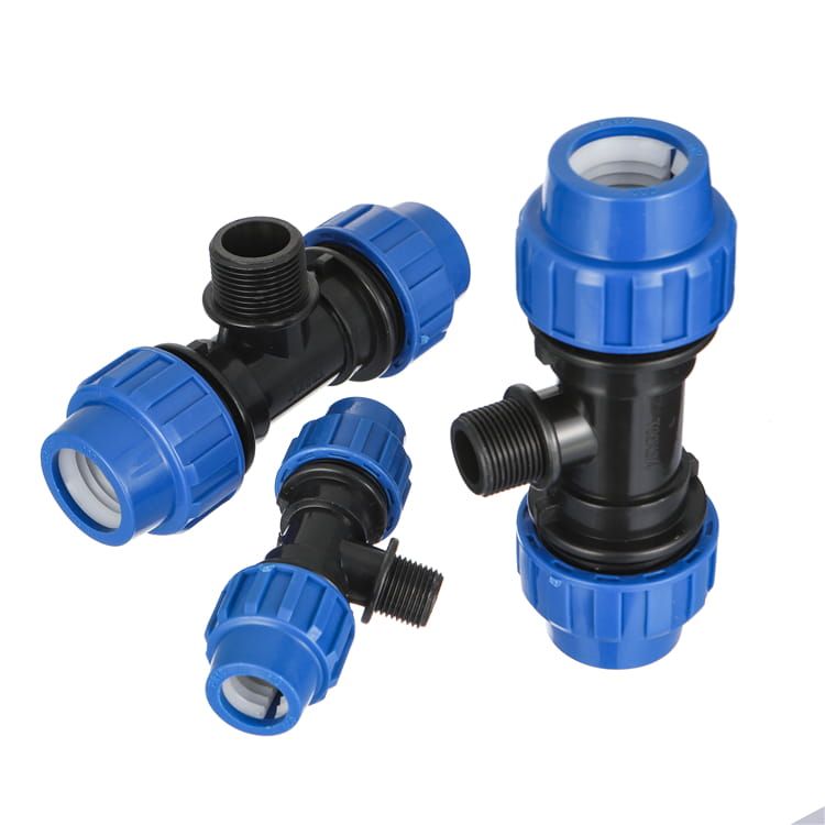
On the smaller grid mains and at every tie-in, repair, and awkward-geometry connection, electrofusion earns its higher fitting cost by needing far less working space and far less pipe end movement. At every interface with a valve, pump, meter chamber or existing metallic main, you need a flanged connection — a stub end with a backing ring — because that is the only joint you can undo. And on the service layer, compression fittings dominate: they need no power, no fusion certification, and they can be made by a two-person crew in a small pit.
The insider warning on jointing strategy is about qualification, not method. HDPE fusion joints are only as good as the operator and the recorded parameters, which is why serious specifications require fusion technician qualification and a joint data record for every main-line weld. If your tender does not ask for joint reports, you will not get them, and you will have no way to investigate the one weld that fails eighteen months later. The mechanics of each method, including the pressure and heat-soak sequences, are covered in the butt fusion vs electrofusion comparison and the full method roster in the HDPE joint types guide.
The fittings and valves takeoff: count geometry, not percentages
This is the section that decides whether your order arrives complete. The common shortcut — budgeting fittings as a percentage of pipe cost — is an estimating convention, not a takeoff, and it fails on networks because the fittings count is driven by topology, not by length. Two 4 km networks with identical pipe schedules can differ by a factor of three in fitting count if one is a looped grid feeding street frontages every 40 m and the other is a rural transmission line with four offtakes.
The reproducible method is to derive quantities from four geometric inputs you already have on the drawing: total main length, average branch spacing, valve policy, and the number of service connections. From those, the counts fall out arithmetically. Branch points equal main length divided by branch spacing. Tees equal branch points.
Bends are counted directly off the alignment, remembering that HDPE's flexibility lets you sweep long-radius direction changes in the pipe itself and only fit a moulded bend where the deflection exceeds the manufacturer's minimum bend radius — which is one of the genuine cost advantages of HDPE over rigid materials and one that estimators routinely forget to take. Sectioning valves follow whatever isolation policy the utility mandates, typically one at each branch off a main and enough on the loop that any single burst can be isolated without dewatering the whole grid. Flange sets equal the number of valves plus every connection to non-HDPE infrastructure.
Worked through on a concrete case, the arithmetic is unambiguous. Take a 4,000 m distribution grid in DN160 with branches averaging every 60 m, a valve at every branch off the main, and 240 service connections in DN25. Branch points: 4,000 ÷ 60 = 66.7, so 67 tees. Sectioning valves: 67 at the branches, plus a conservative 8 for loop isolation and washouts, gives 75, and 75 valves means 150 flange sets — a stub end and backing ring on each side — plus gaskets and bolt sets for each.
Service connections: 240 saddle takeoffs on the main, 240 ferrule or service valves, and at minimum two compression couplers per service, so 480 couplers before any allowance for pit geometry, which in practice pushes it toward 600 to 700 once each connection needs an elbow at the meter and a straight coupler at the boundary. The headline is the ratio: 4 km of pipe generates roughly 67 tees, 75 valves, 150 flange sets and something over 1,000 individual small fittings. The fittings are the piece-count problem, and they are what gets under-ordered.
Two practical notes on this takeoff. First, the numbers above are a worked illustration derived from stated geometry — run the same arithmetic on your own drawing rather than adopting these figures, because branch spacing is the input that swings the result most violently. Second, add a defined breakage and offcut allowance to the small fittings, not to the pipe. Pipe offcuts on a network get reused; a cracked compression nut does not, and a site that runs out of DN25 couplers at 4 pm on a Friday stops.
Pricing a network bill of materials?
This is for contractors, project buyers and importers pricing a whole network rather than a single size — the case where a mixed takeoff of mains, service pipe, tees, valves and flange sets has to land in one shipment. IFAN manufactures PE100 pipe from DN20 to DN1600 alongside the compression, electrofusion, butt-fusion, saddle and flange fittings that go with it, at a one-container MOQ with mixed sizes accepted, so a full network BOM does not have to be split across suppliers with different resin batches.
Trenching, bedding and why HDPE changes the thrust question
Buried HDPE is a flexible pipe, which means the soil around it is part of the structure. The embedment does the work of resisting deflection, so bedding specification is not boilerplate. The PPI/Alliance for PE Pipe model specification calls for embedment material of Class I, II or III as defined by ASTM D2321 Section 6, with bedding to Section 8 and haunching and backfill to Section 9, compacted in excess of 85% Proctor. Class IV and V materials are explicitly not recommended.
The haunch zone — the wedge of material under the pipe springline — is the part crews skip when they are behind schedule, and it is the part that determines whether the pipe holds its round shape under traffic loading.
Thrust restraint is where HDPE genuinely differs from ductile iron or PVC and where specifications get copied across from the wrong material. On a rigid-pipe network with mechanical joints, every bend, tee and dead end needs a thrust block, because the joints cannot carry longitudinal load.
A fused HDPE network is a continuous, fully restrained monolithic string — the joints are as strong as the pipe — so thrust blocks at fused fittings are generally unnecessary. What HDPE has instead is a longitudinal force problem at transitions: at the point where a fused string ends in a mechanical joint or a flange, the Poisson effect pulls on the anchor when the line is pressurized.
Those forces are large enough to be worth designing rather than eyeballing. Pressurized to 1.5 times its pressure class, a 12 in. DIPS DR11 PE line generates a longitudinal Poisson thrust of 17,727 lbs; the same size in DR17 generates 11,753 lbs, and an 8 in. DR11 generates 8,112 lbs.
The PPI field manual for municipal water applications works the anchor sizing through: at 17,727 lbs against a presumptive soil bearing strength of 1,000 lbs per square foot, that is 17.7 square feet of block contact area, and applying a 1.5 safety factor gives 26.6 square feet required.
For reference, presumptive bearing values run 1,500 psf for sand and gravel, 2,000 psf for compacted sand and gravel or crushed stone, and 4,000 psf for hard pan — so the same anchor on crushed stone halves in area. Note also that this force appears during pressure testing, not just in service, which is why anchors have to be in place and cured before the test rather than after it.
Pressure testing and disinfection: the handover gate
Start with the rule that overrides everything else on this topic. Pneumatic leak testing of HDPE pressure piping is prohibited for safety reasons, and where hydrostatic testing is specified you never substitute compressed gas. This is not a preference. A catastrophic failure during a pressurized liquid test dissipates its energy quickly; the same failure under compressed gas releases many times the energy, more forcefully and for longer. Field leak testing of PE pressure piping is governed by ASTM F2164, whose scope covers testing by filling with a liquid and applying pressure, and which states outright that it does not address leak testing using a pressurized gas.
HDPE also behaves differently under test than rigid pipe, and crews used to ductile iron misread it. PE is viscoelastic: when you pressurize it, the pipe expands, and it keeps expanding for a while. That expansion consumes make-up water and shows as a falling pressure, which looks exactly like a leak to someone reading a gauge.
A valid PE test needs an initial expansion phase before the test phase, and the allowable test pressure itself falls as the test gets longer — the leak-test duration factor is 1.5 for tests up to 8 hours, 1.25 for up to 48 hours, and 1.00 for up to 120 hours.
Test pressure is also temperature-sensitive: the test fluid and test section should be below 80 °F (27 °C), and above that a reduced test pressure is required. Black PE strung out in the sun before lowering-in can be well above ambient, which is a real risk on African and Middle Eastern projects and a reason to lower and backfill before testing rather than after.
A widely used municipal acceptance criterion for completed water piping is 1.5 times the system working pressure or 150 psi, whichever is greater, held for 2 continuous hours — and short-term pressure leak tests on PE can run at 1.5 times the listed pressure rating. Treat those as an example of what a specification typically demands rather than a universal rule; the governing figure is whatever your jurisdiction's water authority writes into the contract, and it should be read together with the ASTM F2164 expansion-phase procedure rather than instead of it.
Disinfection is where a PE-specific limit gets missed almost universally, and it is worth putting in your specification in bold. New water mains are flushed and disinfected in accordance with ANSI/AWWA C651, and chlorine disinfection within those guidelines does not significantly harm PE pipe performance.
Under the common continuous-feed and tablet methods that means introducing water containing a minimum of 25 mg/L free chlorine until the entire new pipe holds that concentration, retaining it for at least 24 hours and no more than 48 hours, then flushing and taking bacteriological samples — typically every 1,200 feet of new main plus one set from the end of the line and at least one from each branch.
But the PE model specification adds a constraint the generic disinfection clause does not carry: disinfection chemicals should be limited to less than 12% active chlorine, and the disinfection duration should not exceed 24 hours. A contractor reaching for a stronger hypochlorite solution to save time on a hot site is outside the PE guidance even while staying inside a generically-written C651 clause. Requirements vary by jurisdiction and by water authority, so confirm the governing disinfection procedure with the receiving utility before commissioning.
What to check before you accept a network shipment
Documentation on a network order is not a formality, because the pipe is going in the ground for fifty years and the markings are the only evidence anyone will ever have. Run this list against the delivery, not against the quotation.
- Marking interval and content on the pipe. ASTM, AWWA, NSF and CSA standards require markings at frequent intervals — generally not less than every 5 feet — carrying nominal size, PE material type, the DR or pressure rating, the standard the pipe was made and tested to, the manufacturer's name or trademark, production record coding for place and time of manufacture, and the certification agency seal for potable service. A pipe marked only with a size and a brand is not specification-compliant, whatever the quotation said.
- The fittings' own certification mark, separately. This is the one buyers skip. Fittings should carry the manufacturer's name or trademark and the nominal size, plus the seal of the agency certifying the fitting material for potable water service. Certification on the pipe does not certify the fittings, and on a network the fittings are where the piece count lives.
- Potable-water scope, item by item. NSF/ANSI 61 sets minimum health-effects requirements for contaminants imparted to drinking water and covers pipes and fittings, joining and sealing materials such as gaskets and lubricants, and mechanical devices including valves — as separately certified items. Certification is established by leachate testing, not by declaration, and it replaced the US EPA Additives Advisory Program for these components. If your jurisdiction requires NSF-61, require the mark on every wetted item, including the gaskets and the fusion lubricant.
- Batch traceability against the shipment. Material certificates should tie to the production coding on the pipe you actually received, not to a generic type-test report. IFAN issues batch material certificates per shipment and holds ISO, CE and SGS third-party certification, with regional certificates such as SASO, SONCAP and NOM available on request — the certificate scope should be checked against what your destination market's authority actually demands before the container is booked, since regional approval regimes differ.
- Contaminated-ground check. ISO 4427-2:2019 states plainly that pipes complying with it are not intended to convey water for human consumption in contaminated soils unless special consideration has been taken. If any part of the alignment crosses a former fuel station, workshop or landfill, that is a specification decision — a barrier-layer pipe or a rerouted alignment — and it has to be made before the pipe is ordered.
- Tracer wire on the schedule. HDPE does not conduct, so a buried network is invisible to standard locating equipment without it. Code families such as IRC 2024 require continuous, non-spliced tracer wire — typically 12 AWG or larger insulated copper, or PE-jacketed steel — laid within 6 inches of the pipe with accessible terminations, with blue the APWA convention for potable water. Confirm the gauge, colour and termination detail against your local code, and make sure the wire is a line item, because it is not supplied with the pipe.
Is HDPE the right material for your network?
A specification guide that never says "not this" is marketing. HDPE is the default for most new water supply networks for good reasons — fused joints do not leak, the material does not corrode or tuberculate, coils reduce joint counts on service runs, and the flexibility that lets it sweep bends also lets it survive ground movement. But it is not universally correct, and the honest boundaries are worth stating.
| Best for | Not the best choice for |
|---|---|
| Buried potable mains and service networks where leak-tight fused joints matter | Alignments through hydrocarbon-contaminated ground without a barrier-layer solution |
| Ground-movement, seismic and settlement-prone routes | Hot-water or elevated-temperature service, which needs PPR, PEX or PE-RT instead |
| Trenchless crossings, directional drilling and slip-lining rehabilitation | Projects with no access to qualified fusion crews or fusion equipment on the mains |
| Long service runs where coiled pipe eliminates joints | Exposed above-ground runs with no UV or mechanical protection detailing |
| Networks needing one supplier across service and transmission diameters | Very short repair sections where matching the existing rigid material is simpler |
Where HDPE competes directly against PVC or PPR on a given network, the trade-offs are set out in the HDPE vs PVC and PPR comparison. For buyers in Africa and other markets where landed cost and container efficiency drive the decision as much as the hydraulics do, the HDPE supply guide for African projects covers the shipping and documentation side.
What IFAN supplies against a network takeoff — and where we stop
Since this guide argues that a network should be bought as one matched package, it is fair to state precisely what that means here and what it does not. IFAN produces PE100 pipe from DN20 to DN1600. That range is the reason a network can be a single order: DN20 to DN75 falls inside the AWWA C901 service band of 19–76 mm, DN110 upward falls inside the C906 distribution and transmission band, and DN1600 sits against C906's 1,650 mm ceiling. One resin specification, one marking convention, and one accountable party across both halves of the network.
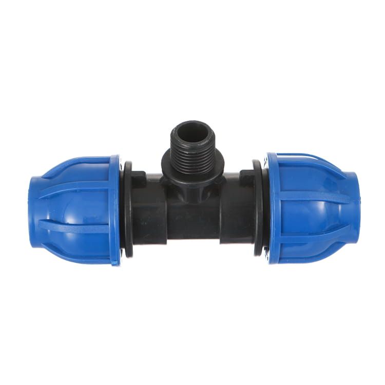
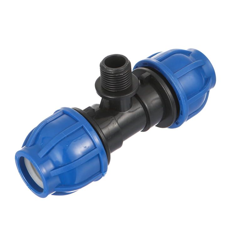
The fitting families that a takeoff actually consumes are made in-house rather than bought in, and they sit together in the HDPE pipe and fitting catalogue: compression couplers, adaptors, elbows, tees, reducers and compression ball valves for the service layer; electrofusion couplers and butt-fusion fittings for the mains; saddle clamps for branch takeoffs; and stub-end-and-backing-ring sets for every flanged interface. The manufacturing base behind that is a 120,000 m² facility in Zhejiang running 30+ automated extrusion lines with in-house injection moulding, a mould workshop and an ISO testing lab, exporting to 120+ countries since 1993.
The commercially useful number for a project buyer is the MOQ: one container, with mixed sizes accepted. A network BOM is by definition mixed — DN160 mains, DN25 services, 67 tees, 75 valves, 150 flange sets — and per-SKU minimums are what normally force that BOM to be split across suppliers, which is how fittings end up arriving from a different resin batch than the pipe they seal against. On documentation, every shipment carries batch material certificates, and the company holds ISO, CE and SGS third-party certification, with SASO, SONCAP and NOM available on request.
Where we stop is worth stating just as plainly. IFAN's documented certificate scope is the batch material certificates and the ISO, CE and SGS marks above — this article does not claim NSF/ANSI 61 listing or AWWA C901/C906 listing for IFAN product, because those are separate certification regimes with their own testing and their own marks. If your jurisdiction requires either, ask for that specific evidence from any supplier, this one included, and check it against the destination authority before booking the container rather than after. A supplier who answers a certification question with a general quality statement has answered a different question.
A network specified end to end: worked example
Putting the whole sequence together on one illustrative project makes the dependencies visible. Take a small-town distribution scheme: a 1,200 m transmission main from an elevated tank, a 4,000 m looped distribution grid, and 240 service connections. Static head at the lowest point gives a working pressure of about 100 psi, and the design velocity in the main is 1.5 m/s — roughly 5 fps.
Grade first: PE100 throughout, fixed across all three layers so every fusion joint is between compatible material. Mains SDR next: at 100 psi working pressure the pressure-class table alone would allow DR21, but the surge check governs. At 5 fps the PPI worked example shows DR21 passing all three checks — yet the margin is thin enough that any future demand growth pushing velocity to 6 fps would breach the recurring-surge allowance, at which point DR17 becomes necessary.
Because this network is explicitly designed for a growing town, the defensible specification is DR17 for the transmission main and grid now rather than an upgrade dug up later. That single decision — made on velocity headroom, not on today's pressure — is the difference between a network that absorbs growth and one that gets re-laid.
Services: DN25 at the same pressure class as the grid, coiled, with compression fittings. Jointing strategy: butt fusion on the transmission main and the DN160 grid, electrofusion reserved for tie-ins and repairs, flanged stub-end-and-backing-ring sets at all 75 valves and at the tank connection, compression on all 240 services. Takeoff from geometry: 67 tees at 60 m branch spacing, 75 valves, 150 flange sets, 240 saddle takeoffs and upward of 600 small compression fittings.
Installation: Class I–III embedment compacted above 85% Proctor, anchors sized for the Poisson force at each fused-to-mechanical transition and cured before testing. Commissioning: hydrostatic test only, with the initial expansion phase allowed for and the test kept under 8 hours to stay on the 1.5 duration factor; then C651 disinfection at 25 mg/L held 24 to 48 hours, using a hypochlorite below 12% active chlorine and a disinfection duration inside 24 hours, then flushing and bacteriological sampling every 1,200 feet plus the line end and each branch before handover.
Nothing in that sequence is exotic. What makes it work is that each decision was made in the right order, with the surge check ahead of the SDR choice and the takeoff derived from geometry rather than from a percentage. Networks fail commercially at the joins between those steps, not inside them.
Conclusion
An HDPE water supply network is specified in layers, and the discipline is keeping the layers consistent: one resin grade, an SDR chosen against surge at the design velocity rather than against steady pressure, a documented jointing rule per layer, a fittings takeoff derived from network geometry, and a commissioning procedure that respects the fact that PE tests and disinfects differently from iron.
The standards do most of the work if you cite the right ones — the AWWA C901/C906 split at 3 in./4 in. or the single ISO 4427 family covering mains and services together — and the surge allowances of 1.5 × PC recurring and 2.0 × PC occasional are the numbers to design to.
If you are pricing a network rather than a pipe size, the practical question is whether your BOM can be sourced as one matched package across the service and transmission bands. Send the alignment length, branch spacing, working pressure and connection count, and the takeoff can be built from there.
Frequently Asked Questions
What SDR should I use for an HDPE water main?
Choose it by surge, not steady pressure. Working pressure must sit inside the pressure class, working plus occasional surge under 2 × PC, and working plus recurring surge under 1.5 × PC. Velocity drives the result.
Can the same HDPE pipe be used for mains and service lines?
The same resin grade should be, so fusion joints stay compatible. The sizes differ: AWWA C901 covers service pipe 19–76 mm, AWWA C906 covers distribution and transmission 100–1,650 mm. ISO 4427 covers both in one family.
Can I pressure test an HDPE network with compressed air?
No. Pneumatic leak testing of HDPE pressure piping is prohibited for safety reasons, because a failure under compressed gas releases far more energy. Use hydrostatic testing per ASTM F2164.
Does an HDPE network need thrust blocks at every bend?
Generally no. A fused HDPE string is self-restrained, so fused fittings rarely need blocks. Anchors are needed where a fused string transitions to a mechanical or flanged joint, sized for the Poisson force.
Why does my pressure test keep losing pressure with no visible leak?
PE is viscoelastic and expands under pressure, consuming make-up water. That reads as pressure loss. A valid test allows an initial expansion phase first, then measures over the test phase.
Is there a chlorine limit when disinfecting HDPE mains?
Yes, and it is PE-specific. Alongside AWWA C651 procedure, disinfection chemicals should stay below 12% active chlorine and the disinfection duration should not exceed 24 hours. Confirm the procedure with the receiving utility.
Do HDPE fittings need their own potable-water certification?
Yes. Certification on the pipe does not certify the fittings. Fittings should carry the mark of the agency certifying that fitting material for potable service, separately from the pipe marking.